Electronics International MVP-50P User Manual
Page 54
“Powered By”: The device that provides the Flap signal is
normally a control pot. This control pot can be powered by
the aircraft bus (preferred) or the by the EDC. If the control
pot is powered by the aircraft bus, the MVP must do a ratio
metric calculation to insure the flap readings do not change
when the bus voltage changes.
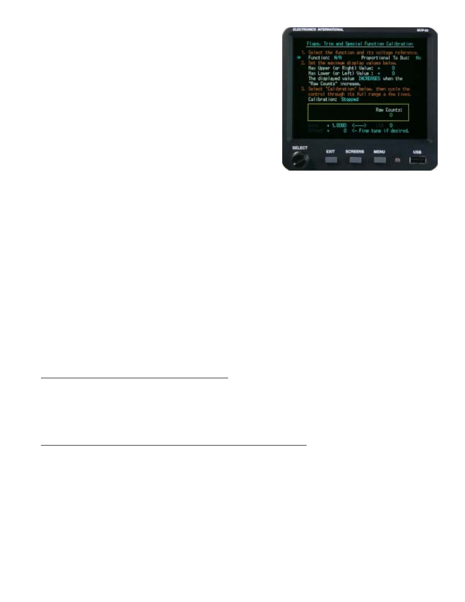
“2. Set the maximum Display values below.”
“Max Upper (or Right) Value:” Enter the maximum up or
right value. This would be “0” degrees for flaps.
“Max Lower (or Left) Value:” Enter the maximum down
or left value. This may be “40” degrees for flaps.
Note: For Trims these values may be +30 degrees to -30 Degrees.
“The display value (INCREASES / DECREASES) when the “Raw Counts” increase.” Determine
whether you want the “Displayed Value” to increase or decrease as the Raw Counts (as shown to the right of
the Horizontal Strip Gauge) increase. You may want to watch the Raw Counts as you cycle the control.
“3. Select “Calibration” below, then cycle the control through its full range a few times.”
The MVP performs an automatic calibration by scaling the maximum and minimum Raw Counts to the “Max
Upper” and Max Lower” values you previously selected above. As you cycle the control through its range a
few times the max and min reading on the Horizontal Strip Gauge should match your programmed values.
“Gain” and “Offset” The automatically calibrated gain and offset values can be changed manually to achieve a
specific Displayed Value for a specific control setting.
6.15 “MVP Input/Output Tests” Screen:
This screen allows you to test the various MVP input and output lines. This screen can be very useful in
troubleshooting system problems.
6.16 “EDC Inputs, Functions and Screen Setup” Section:
Probes and transducers are mechanically connected to the aircraft and are electrically connected to the EDC
(Engine Data Converter). The EDC converts the analog signals from the probes to digital signals and then transmits
them to the MVP. The following screens allow you to display a function on an MVP screen and set the redlines and
limits. The five screens in this section perform the following:
Screen #1: This screen assignes a Function and Probe to an EDC input. The Probe sets the calibration
parameters found in screen #5.
55