Electronics International MVP-50P User Manual
Page 17
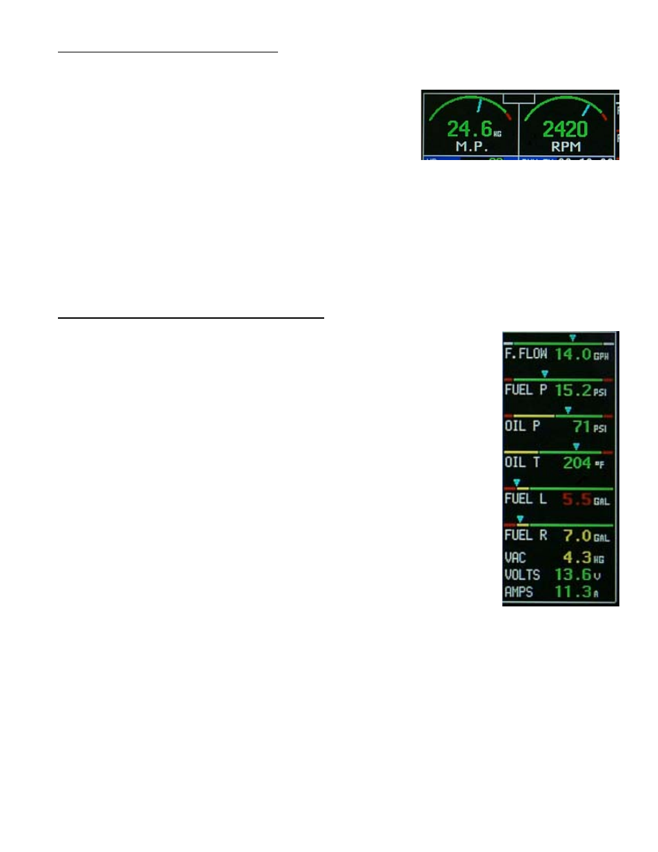
2.3 RPM and Manifold Pressure:
The RPM and M.P. instruments incorporate a digital readout and an
analog arc. The color of the digital readout will reflect the current range
in witch the function is operating (i.e., if the RPM is operating in the red,
the digital readout will be red).
The digital display can be set to blink when the RPM or M.P. operating
level reaches a yellow or red operating range. To stop the blinking,
push any button, or rotate the SELECT knob. Also, acknowledging a voice warning using the external “Voice
Alarm Control Panel” will stop the blinking of any digital display.
The MVP’s RPM Instrument provides a Mag Out feature in addition to the arc and digital display. The MVP
continually monitors both mag signals. If one mag fails, an appropriate “L. Mag Out” or “R. Mag Out” warning will
be displayed on the appropriate side of the RPM digital display.
2.4 Horizontal Strip and Digital Gauges:
The six Horizontal Strip and three Digital Gauges provide the following features:
A. The colored operating ranges shown on the Horizontal Strip can be set up for
any aircraft.
B. Each Horizontal Strip Gauge features a pointer (triangle) marking the current
operating level. Also, the pointer allows the pilot to interpret rate and trend
information and provides field of vision.
C. A digital display is featured with each Horizontal Strip Gauge.
D. The digital will blink when a function’s operating level reaches a yellow or red
operating range. To stop the blinking, push any button, or rotate the Select
knob. Also, acknowledging a voice warning using the external “Voice Alarm
Control Panel” (experimental only) will stop the blinking of any digital display.
12
L. Mag
Out