Troubleshooting, Troubleshooting the lcr 600 – Liquid Controls FlightConnect 600 User Manual
Page 45
45
troubleshooting the lcr 600
The troubleshooting section of this manual covers common problem situations. Call your local authorized Liquid
Controls service provider or the Liquid Controls electronics service department if the troubleshooting section does not
address the situation.
When troubleshooting the LCR 600 follow these guidelines:
• Check for proper operating voltages before changing the circuit board. If the circuit board needs to be changed, be sure to remove all
power to the LCR 600.
• The error message or a diagnostic ticket will contain an error message that can be useful in troubleshooting. Examine the diagnostic
screens on the LCR 600 or the diagnostic ticket to make sure all set-up fields are accurate, e.g. pulses per unit volume, temperature
coefficient and base temperature. Print a diagnostic ticket by moving the red selector switch to “SHIFT PRINT” for less than two
seconds.
• Never remove a terminal block or jumper with the power on.
• Never install a terminal block or jumper with the power on.
• Never force a terminal block into its location.
• Never exchange or reposition terminal blocks on the circuit board.
• In case of a major problem such as a burned or water-damaged circuit board, evaluate possible causes before replacing it and
turning the power back on.
• Isolate the problem before changing the circuit board.
• Return faulty circuit boards with the proper forms, concisely completed, to a LC service provider.
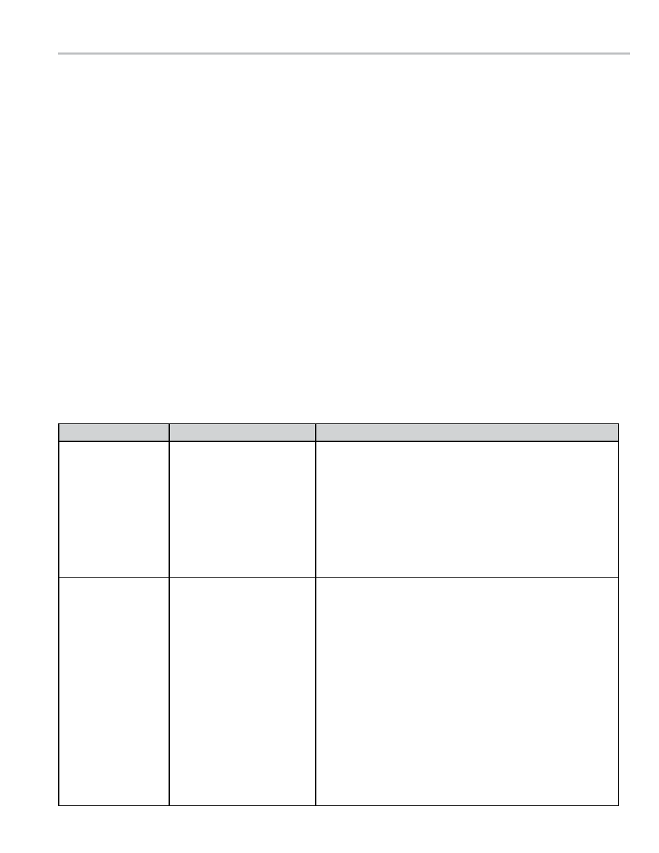
problem
probable cauSe
SolutIon
unit will not power
up or no display.
1. Inadequate supply
voltage. 9 to 28 VDC is
required for operation.
1. With the key in the accessory position, check the battery
voltage to the circuit board at J6. Use terminal #11 as
positive and terminal #12 as DC ground. While the LCR
600 will power-up at 9 VDC, it is recommended that the
input be at least 12.6 VDC. Voltage less than 12 VDC
may cause failures in equipment connected to the LCR
600, such as valves or external displays
2. Check the 7.5 A, in-line fuse (PN 70985) for continuity.
It is located on the accessory power line. Replace if
necessary.
unit blows 7.5 a
fuse.
1. 12 VDC Battery line is
shorted to ground.
1. For safety reasons, remove the 7.5 A in-line fuse from
the accessory power cable.
2. Remove the J6 terminal block. Inspect for stray wire
stands and visible shorts.
3. Using a multimeter, take a reading across terminal 11
and terminal 12 on the J6 terminal block. The terminals
should be open. If the multimeter shows a short, replace
the power cable (PN 81512).
4. Inspect the length of the power cable for damaged
insulation that could cause a short between the wire
and the chassis (or other nearby metal). If the cable is
damaged, replace it.
5. Replace the 7.5 A fuse (PN 70985) and re-install the J6
connector.
6. If the 7.5 A fuse blows again, replace the LCR 600 circuit
board.
troubleShootIng