GF Signet 8350 Temperature Transmitter User Manual
Page 2
2
8350-3 Temperature Transmitter
10
9
8
7
6
5
4
3
2
1
16
15
14
13
12
11
Output 2-
Output 2+
Output 1-
Output 1+
Loop 2-
Loop 2+
System Pwr
Loop -
System Pwr
Loop +
AUX
Power -
AUX
Power +
Snsr 2 Gnd
(WHITE)
Snsr 2 IN
(RED)
Snsr 2 V+
(BLACK)
Snsr 1 Gnd
(WHITE)
Snsr 1 IN
(RED)
Snsr 1 V+
(BLACK)
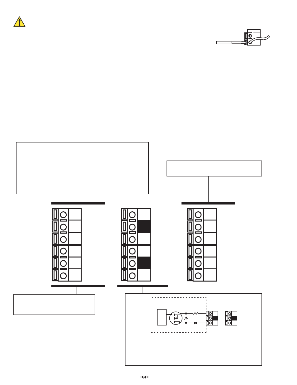
3. Electrical
Connections
Caution: Failure to fully open terminal jaws before removing wire may permanently damage instrument.
Wiring Procedure
1. Remove 13 mm - 16 mm (0.5 in. - 0.625 in.) of insulation from wire end.
2. Press the orange terminal lever downward with a small screwdriver to open terminal jaws.
3. Insert exposed (non-insulated) wire end in terminal hole until it bottoms out.
4. Release orange terminal lever to secure wire in place. Gently pull on each wire to ensure a good connection.
Wiring Removal Procedure
1. Press the orange terminal lever downward with a small screwdriver to open terminal jaws.
2. When fully open, remove wire from terminal.
Wiring Tips:
• Do not route sensor cable in conduit containing AC power wiring. Electrical noise may interfere with sensor signal.
• Routing sensor cable in grounded metal conduit will help prevent electrical noise and mechanical damage.
• Seal cable entry points to prevent moisture damage.
• Only one wire should be inserted into a terminal. Splice double wires outside the terminal.
• If your system uses a single sensor, it must be located within 122 m (400 ft.) of the transmitter.
• If your system uses two sensors, the total length of cable connected to the transmitter is limited to 122 m (400 ft.)
• The 3 conductors from a dual-sensor system can be tied together and then a single set of wires continued on to the transmitter.
• For best performance, ground the sensor SHIELD wire to a local earth ground at a point near the sensor.
(Experiment by connecting the sensor shield wire to different local ground points to identify best signal quality.)
2
1
1
15
S
D
2
_
+
Internal open-collector
output circuit
Outputs
Isolation
Terminals 7-10: Open-Collector Outputs
Two transistor outputs, programmable (see CALIBRATE menu) as:
• High or Low setpoint with adjustable hysteresis
• Proportional pulse output
• May be disabled (Off) if not used.
Terminals 11-16: Dual digital sensor inputs
See next page for more information.
Terminals 3-4: Primary Loop Power
12-24 VDC ±10% system power and current loop connections.
SINGLE SENSOR system MUST use terminals 3-4.
Terminals 5-6: 12-24 VDC ± 10%
Power and current loop connections for second sensor.
• Maximum loop impedance:
50 Ω max. at 12 V
325 Ω max. at 18 V
600 Ω max. at 24V
Terminals 1-2: Auxiliary power is used
only if two sensors are connected to
the transmitter.