Wiring: 4 to 20 ma output, S1 s2, Normally closed common normally open – GF Signet 2537 Paddlewheel Flow Sensor User Manual
Page 5
5
Signet 2537 Flowmeter
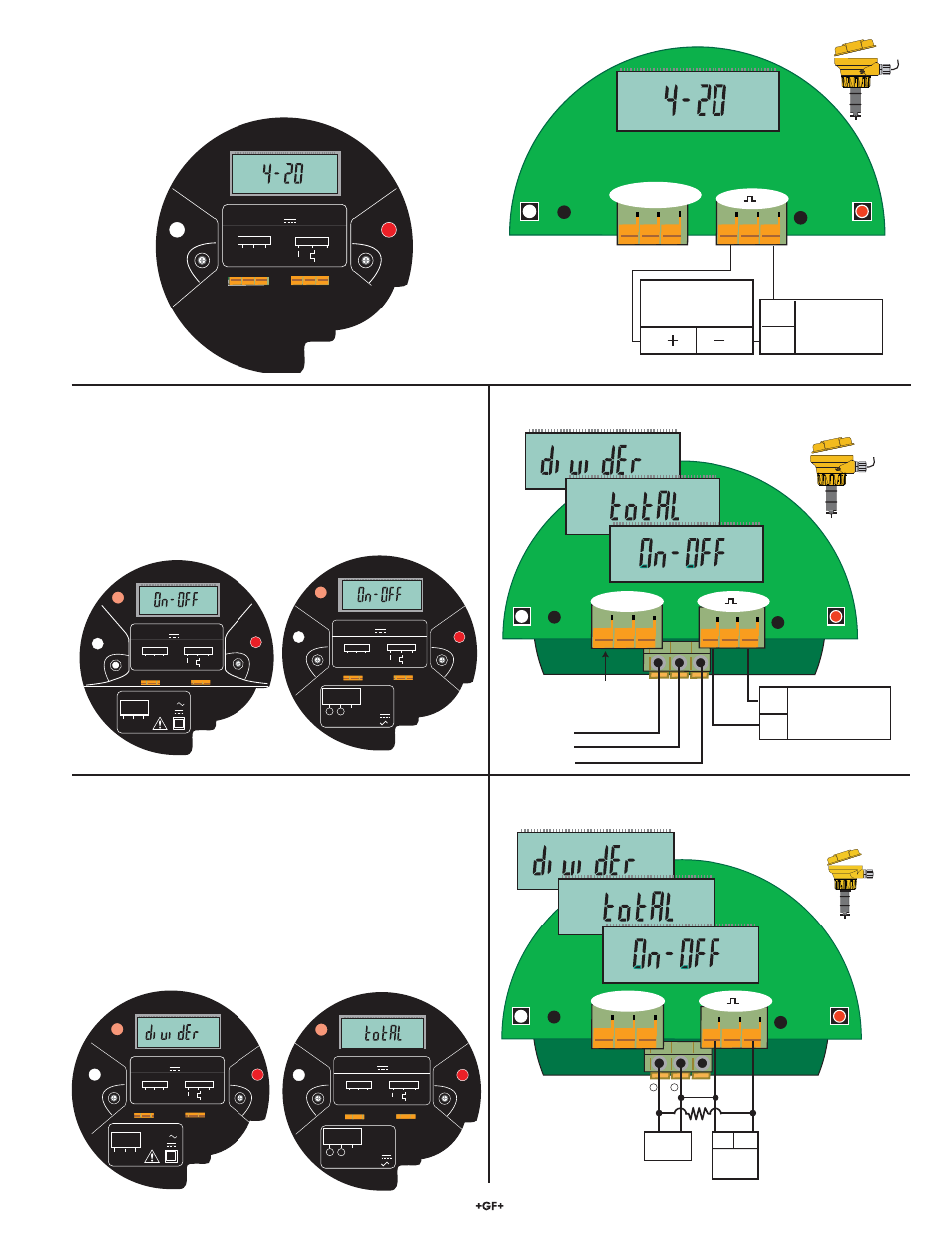
Wiring: 4 to 20 mA Output
S1
S2
Power Supply
12 to 32 VDC, 0.03 A
+
-
Blk Red Shld
-
+
Programmable Logic Controller
Datalogger
Chart Recorder
4 to 20 mA Loop monitor
Internal sensor
connections
The 4 to 20 mA output can be connected to Chart Recorders, PLCs or
any device that requires a 4 to 20 mA signal.
The 4 to 20 mA model requires an external power source of
12 to 32 VDC.
Wiring: Flow Switch Output (On-OFF)
• The Flow Switch mode allows a single relay that is
programmable as a HIGH setpoint or LOW setpoint.
• The relay may be a dry-contact type or a solid state type.
• The dry contact relay requires an external power source of
24 VDC ± 10%.
• The solid state relay requires an external power source of
5 to 24 VDC.
Dry Contact Relay Wiring
• The wiring is identical for On-OFF and Pulse modes.
Solid State Relay Wiring
• The wiring is identical for On-OFF and Pulse modes
.
Wiring: Pulse Output
• The "Multi" mode allows a single relay that is programmable
as a Flow Switch, Volumetric pulse output or as a simple pulse
divider output.
• The relay may be a dry-contact type or a solid state type.
• The Dry Contact Relay requires an external power source of
24 VDC ± 10%.
• The Solid State Relay requires an external power source of
5 to 24 VDC.
• Solid State Relay requires a pull-up resistor (10K ohm
recommended). Consult your instrument/PLC manual for
wiring information.
S1
S2
Power Supply
24 VDC, 0.03 A
+
-
Normally Closed
Common
Normally Open
Blk Red Shld
-
+
Internal sensor
connections
S1
S2
Power Supply
5 to 24 VDC,
0.03 A
Blk
Red Shld
-
+
1
2
Load
+
–
I/O
10KΩ
S1
S2
Blk Red Shld
-
-
+
-
+
-
+
-
+
-
+
-
+
T
P
t
T
P
t
T
P
t
T
T
P
P
t
t
WIRING DIAGRAM
BLK
RED
SHLD
Sensor
PW/OUT
+
Power Rating:
12 - 32VDC 0.03 AMP
3-2505.614A
-
+
-
+
-
+
-
+
S1
S2
Blk Red Shld
-
-
+
+
S1
S2
Blk Red Shld
-
-
+
+
T
P
t
T
T
P
P
t
t
T
T
P
P
t
t
WIRING DIAGRAM
BLK
RED
SHLD
Sensor
PW/OUT
+
Power Rating:
5 - 24VDC 0.03 AMP
3-2505.612A
WIRING DIAGRAM
BLK
RED
SHLD
Sensor
PW/OUT
+
Power Rating:
24VDC 0.03 AMP
3-2505.61
1A
Solid-State
Relay
Relay Rating:
100mA @ 40VDC
70mA @ 33VAC
3-2505.616A
Load
1 2
N/O
COM
N/C
Dry-Contact
Relay
Relay Rating:
5A @ 250VAC
5A @ 30VDC
T
P
t
-
+
-
+
S1
S2
Blk Red Shld
-
-
+
+
S1
S2
Blk Red Shld
-
-
+
+
-
+
-
+
T
P
t
WIRING DIAGRAM
BLK
RED
SHLD
Sensor
PW/OUT
+
Power Rating:
24VDC 0.03 AMP
3-2505.61
1A
T
P
t
WIRING DIAGRAM
BLK
RED
SHLD
Sensor
PW/OUT
+
Power Rating:
5 - 24VDC 0.03 AMP
3-2505.612A
T
P
t
Solid-State
Relay
Relay Rating:
100mA @ 40VDC
70mA @ 33VAC
3-2505.616A
Load
1 2
N/O
COM
N/C
Dry-Contact
Relay
Relay Rating:
5A @ 250VAC
5A @ 30VDC
T
P
t