Maintenance, Hot-tap sensor removal – GF Signet 2540 Stainless Steel High Performance Flow Sensor User Manual
Page 7
2540 High Performance Flow Sensor
7
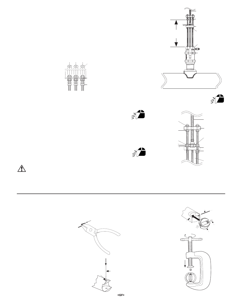
D. Wearing safety face protection, loosen the upper hex nuts and raise to 372 mm (14.6 in.) from top of sensor fi tting to
bottom of upper hex nuts/lock washers. CAUTION! This measurement is critical to maintain watertight seal in
sensor while allowing clearance to close the isolation valve.
E. Wearing safety face protection, turn the installation tool shaft
counterclockwise to withdraw sensor until the sensor fl ange contacts
the upper hex nuts. (Fig. 18)
F. Raise
one lower hex and jam nut to bottom of sensor fl ange.
G. Close isolation valve, remove bearing plate and tool.
H. Wearing safety face protection, cover the bleed valve with suitable
protection (rag, towel, etc.) and open the bleed valve (ccw rotation)
to relieve internal pressure. Pull sensor up until bleed valve purges
some fl uid (indicating sensor is past 1st o-ring seal inside sensor
fi tting).
CAUTION: In case of a leaky isolation valve, the sensor will be under a slight
amount of pressure. Care should be taken when removing the sensor.
Use the bleed valve to relieve this pressure taking care not to spray fl uid on yourself or others.
Sensor can now be safely removed. When reinstalling the sensor: leave one lower hex nut in position to guide sensor to proper
isolation valve clearance height before opening isolation valve. Return to "H" dimension height after valve is opened.
installation tool
threaded shaft
sensor flange
cap nuts
upper hex nuts
1 lower hex nut
and jam nut
sensor body
installation tool
bearing plate
protector plate
hex nuts
swivel mount
w/cable port
Fig. 18
8. Maintenance
Your sensor requires little or no maintenance of any kind, with the exception of an occasional sensor/paddlewheel cleaning.
protector plate
hex nut
protector plate
cap nuts
protector plate
Fig. 16
installation tool
threaded shaft
process pipe (side view)
372 mm
(14.6 in.)
upper hex nuts
and lock washers
sensor flange
lower hex and
jam nuts
UNDER PRESSURE!
sensor fitting
isolation valve
Fig. 17
7. Hot-Tap Sensor Removal
To remove the Hot-Tap sensor safely from a pressurized active pipe, the entire installation
process must be reversed.
A. Remove the cap nuts, protector plate and protector plate hex nuts. (Fig. 16)
B. Thread installation tool in place and secure bearing plate in place of sensor protector plate.
(Fig. 17)
C. Turn shaft of installation tool clockwise to lower tool into opening in sensor fl ange. Guide
cable into the port to prevent damage.
Rotor Replacement Procedure
1. With a small pair of needle-nose
pliers, fi rmly grip the center of the
rotor pin (axle) and with a twisting
motion, bend the rotor pin into an
"S" shape. This should pull the
ends of the pin out of the retainers
and free the rotor assembly.
2. Remove retainer from each side by
gently tapping it inwards using a punch.
Install a new retainer with its rotor pin
clearance hole inward. Only install one
retainer at this time.
Punch
Retainer
Rotor Pin
Rotor Pin
Existing
Retainer
New
Bearings
Rotor
Assembly
3. Insert the new rotor assembly
and bearings into the rotor
housing of the sensor and
place the new rotor pin (axle)
through the open end of
the rotor housing, through
the rotor and bearings, and
into the previously installed
retainer.
4. Using a vise or C-clamp, press
the second retainer into the hole
in the sensor body while lining
up the rotor pin with the center
of the retainer hole.
Note: A hammer and center
punch can also be used if a
clamp or vise is not available.