GF Signet 2540 Stainless Steel High Performance Flow Sensor User Manual
Page 6
2540 High Performance Flow Sensor
6
protector plate
hex nut
protector plate
cap nuts
protector plate
6. Standard Sensor Removal
To remove the sensor from a depressurized empty pipe, simply remove the cap nuts and upper hex nuts located above the sensor
fl ange. Pull up on sensor fl ange with twisting motion.
G. Position the installation tool bearing plate by rotating it so that it is approximately 40 mm (1.6 in.) from the swivel mount. Mount
the installation tool by placing the threaded rods through the holes in the tool's bearing plate, resting the bearing plate on top of
the protector plate hex nuts. Make sure the swivel mount's ears are mounted between the threaded rods (not over the rods).
Install the bearing plate cap nuts. Tighten the bearing plate cap nuts to secure the installation tool in place. (Fig. 13)
H. Align the sensor cable with the swivel mount cable port to prevent cable pinching. Use a 3/8 inch wrench or socket to turn the
installation tool shaft clockwise until it is seated in the hole at the top of the sensor fl ange.
I. Wearing safety face protection, slowly open the isolation valve to the full open position. Loosen the lower hex and
jam nuts and move them to the proper "H" dimension. Turn the installation tool shaft clockwise until the sensor fl ange
contacts the lower hex and jam nuts. Thread the upper hex nuts down until they contact the sensor fl ange. Tighten the
upper hex nuts to secure the sensor. (Fig. 14)
J. Remove cap nuts and withdraw the installation tool. Be careful to not damage cable. Replace protector plate and cap nuts.
(Fig. 15)
swivel mount
w/cable port
installation tool
threaded shaft
sensor flange
bearing plate
cap nuts
protector plate
hex nuts
sensor body
sensor
cable
Hot-Tap Sensor Installation - Continued
Fig. 13
Fig. 14
Fig. 15
"H"
jam nuts
lower hex nuts
alignment rod
installation
tool shaft
cap nuts
upper hex nuts
direction
of flow
isolation valve
25 mm
(1.0 in.)
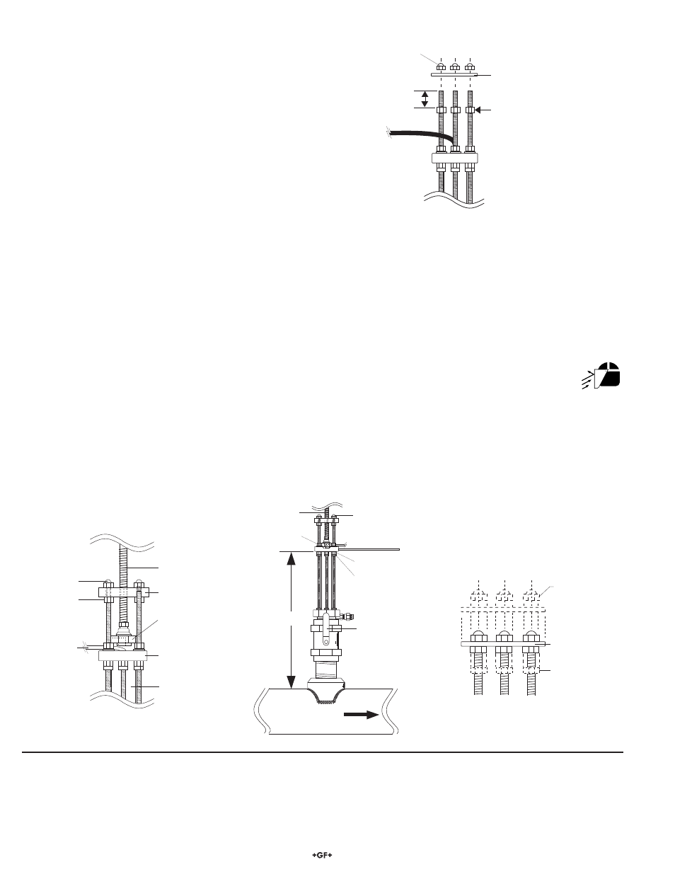
protector plate
hex nut (3/16 x ¼ -20)
protector plate
cap nuts
protector plate
removed during
sensor installation
F. Thread protector plate hex nuts onto each of the three
threaded rods. Adjust each hex nut to a height of
approximately 25 mm (1 in.) from the top of each rod. (Fig. 12)
Fig. 12