Sensor fitting hex nut lock washer – GF Signet 2540 Stainless Steel High Performance Flow Sensor User Manual
Page 5
2540 High Performance Flow Sensor
5
lower hex nut
and jam nuts
sensor flange
18 inch
threaded rods
359 mm (14.14 in)
process pipe (side view)
direction
of flow
alignment rod
Upper hex nuts
(3/16 x 1/4-20)
1/4 in. lock
washers
sensor
fitting
bleed valve
lower hex nuts
(3/16 x 1/4-20)
jam nuts
(5/32 x 1/4-20)
359 mm
(14.14 in.)
sensor
fitting
UNDER PRESSURE!
alignment
rod
sensor
flange
process pipe
(top view)
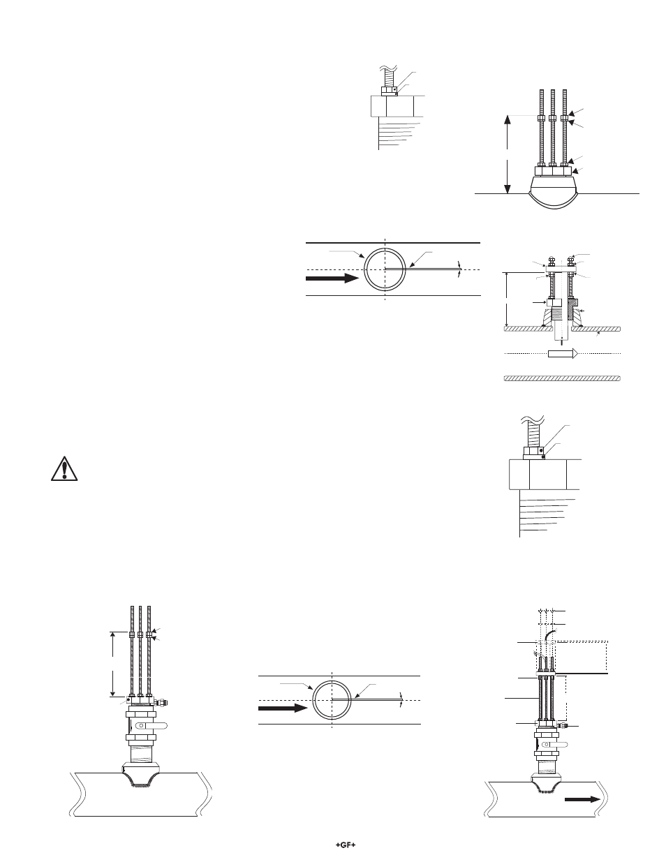
The flow alignment rod MUST be
parallel to the process pipe as shown.
flow direction
Fig. 9
Fig. 10
Fig. 11
D. Place the alignment rod in the alignment hole
on the sensor fl ange. Align the fl ange so rod is
parallel to the process pipe. (Fig. 6)
E. Thread upper hex nuts with lock washers until they
contact the sensor fl ange and tighten. Check for
proper "H" dimension and readjust if necessary.
(Fig. 7)
5.7 Hot-Tap Sensor Installation
A. Thread one hex nut onto each of the three threaded rods included in package. Install threaded
rod with a lock washer onto the sensor fi tting. Secure rods in place by tightening each hex nut
against the sensor fi tting. (Fig. 8)
B. Thread one jam nut and lower hex nut onto each threaded rod so that the top surface of each
nut is 359 mm (14.14 in.) from the top surface of the sensor fi tting. Secure each hex nut with
a jam nut. (Fig. 9)
CAUTION: This setting is critical to ensure an adequate sensor seal and to
prevent the rotor from hitting the isolation valve orifi ce during installation.
C. Wipe the sensor body with a dry, clean cloth. Orient the alignment hole on the sensor fl ange
to point downstream. Place the slotted fl ange over the threaded rods. Lower the sensor into
the fi tting until the sensor fl ange rests on the lower hex and jam nuts.
D. Secure the sensor with lock washers and upper hex nuts on the top of the fl ange. Before
tightening, align the sensor fl ange so that the alignment rod is parallel and level with the
process pipe. (Fig. 10 & Fig. 11)
E. Make sure the bleed valve is closed (full clockwise position).
"H"
process
pipe wall I.D.
sensor
fitting
upper hex nuts
& lockwashers
lower hex nuts
jam nuts
sensor
flange
cap nuts
female pipe fitting
FLOW
sensor fitting
hex nut
Lock washer
alignment
rod
sensor
flange
process pipe
(top view)
The flow sensor alignment rod
MUST be
parallel to the process pipe as shown.
flow direction
Fig. 6
Fig. 7
Fig. 8
5.6 Standard Sensor Installation
A. Thread one hex nut onto each of the three threaded rods
included in package. Install threaded rod with a lock washer
onto the sensor fi tting. Secure rods in place by tightening each
hex nut against the sensor fi tting. (Fig. 4)
B. Thread one jam nut and lower hex nut onto each threaded
rod so that the top surface of each nut is at the proper "H"
dimension for your pipe. Secure each hex nut with a jam nut.
(Fig. 5)
C. Insert the fl ow sensor into the sensor fi tting, making sure the
alignment hole on the sensor fl ange is pointing downstream.
sensor fitting
hex nut
Lock washer
Fig. 4
Fig. 5
process pipe
lower hex nuts
(3/16 x 1/4-20)
jam nuts
(5/32 x 1/4-20)
"H"
sensor fitting
hex nut &
lock washer