Burkert Type 8045 User Manual
Page 33
29
Operatingandfunctions
8.3.
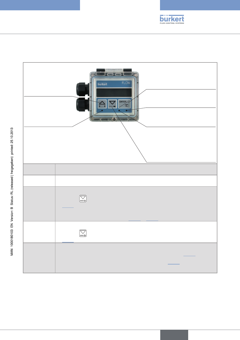
Description of the navigation keys and the status
leDs
• Selecting the displayed
parameter
• Confirming the settings
Status LED of relay DO3 (LED ON
= contact closed)
• Reading the messages
• Scrolling through the parameters
• Selecting the figure on the left
• Scrolling up the
parameters
• increment the figure
selected
Device status LED: see
following table.
Status LED of relay DO2 (LED ON
= contact closed)
Device status
leD
Status of the device
Green
The device operates correctly.
Orange
A warning message is generated.
→
Press the
key for 2 seconds in the Process level to access the message. See chap.
“9.5.5” for the meaning of the message.
Furthermore, a relay output (DO2 or DO3) or the transistor output DO1 switches if it is
configured in the "WARNING" mode (see Fig. 39
or Fig. 42)
Red
A fault message is generated and a 22 mA current is sent on the current output.
→
Press the
key for 2 seconds in the Process level to access the message. See chap.
“9.5.4” for the meaning of the message.
Blinking,
whatever the
colour
• the DI1 digital input is active,
• or a check for the correct behaviour of the outputs is running (see chap. “8.7.3”)
• or a flow zero point calibration procedure is running (see chap. “8.7.2”),
• or the daily totalizer is kept at zero.
English
Type 8045