Burkert Type 8045 User Manual
Page 23
19
Installationandcommissioning
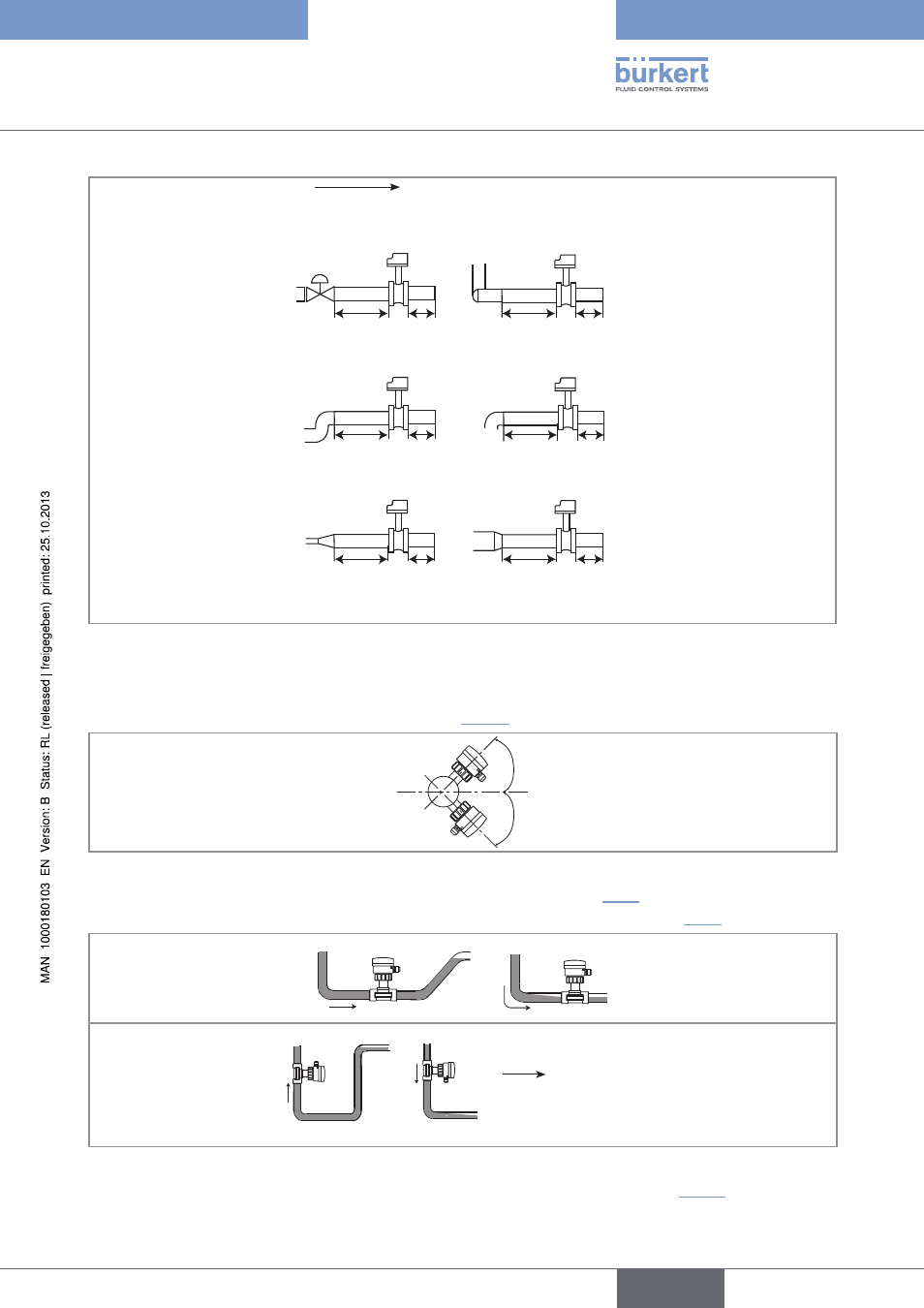
flow direction
50 x DN 5 x DN
40 x DN 5 x DN
25 x DN 5 x DN
20 x DN 5 x DN
18 x DN 5 x DN
15 x DN 5 x DN
With control valve
Pipe with 2 elbows at 90° in 3
dimensions
Pipe with 2 elbows at 90°
Pipe with 1 elbow at 90° or 1
T-piece
With pipe expansion
With pipe reduction
Fig. 7:
Upstream and downstream distances depending on the design of the pipes.
→
Respect the following additional mounting conditions to ensure that the measuring device operates correctly:
- Preferably install the device at a 45° angle to the horizontal centre of the pipe to avoid having deposits on the elec-
trodes and false measurements due to air bubbles (see “Fig. 8”);
45°
45°
Fig. 8:
Mounting angle on the pipe
- Ensure that the pipe is always filled in the section around the device (see Fig. 9).
- When mounting vertically ensure that the flow direction is in an upward direction (see Fig. 9).
Horizontal mounting
Correct
Incorrect
Vertical mounting
Correct
Incorrect
flow direction
Fig. 9:
Filling of the pipe
- Prevent the formation of air bubbles in the pipe in the section around the device (see Fig. 10).
English
Type 8045