Terminal assignement and use of the selectors, Source sink current source sink current, Off on – Burkert Type 8045 User Manual
Page 28
24
Installationandcommissioning
7.3.3.
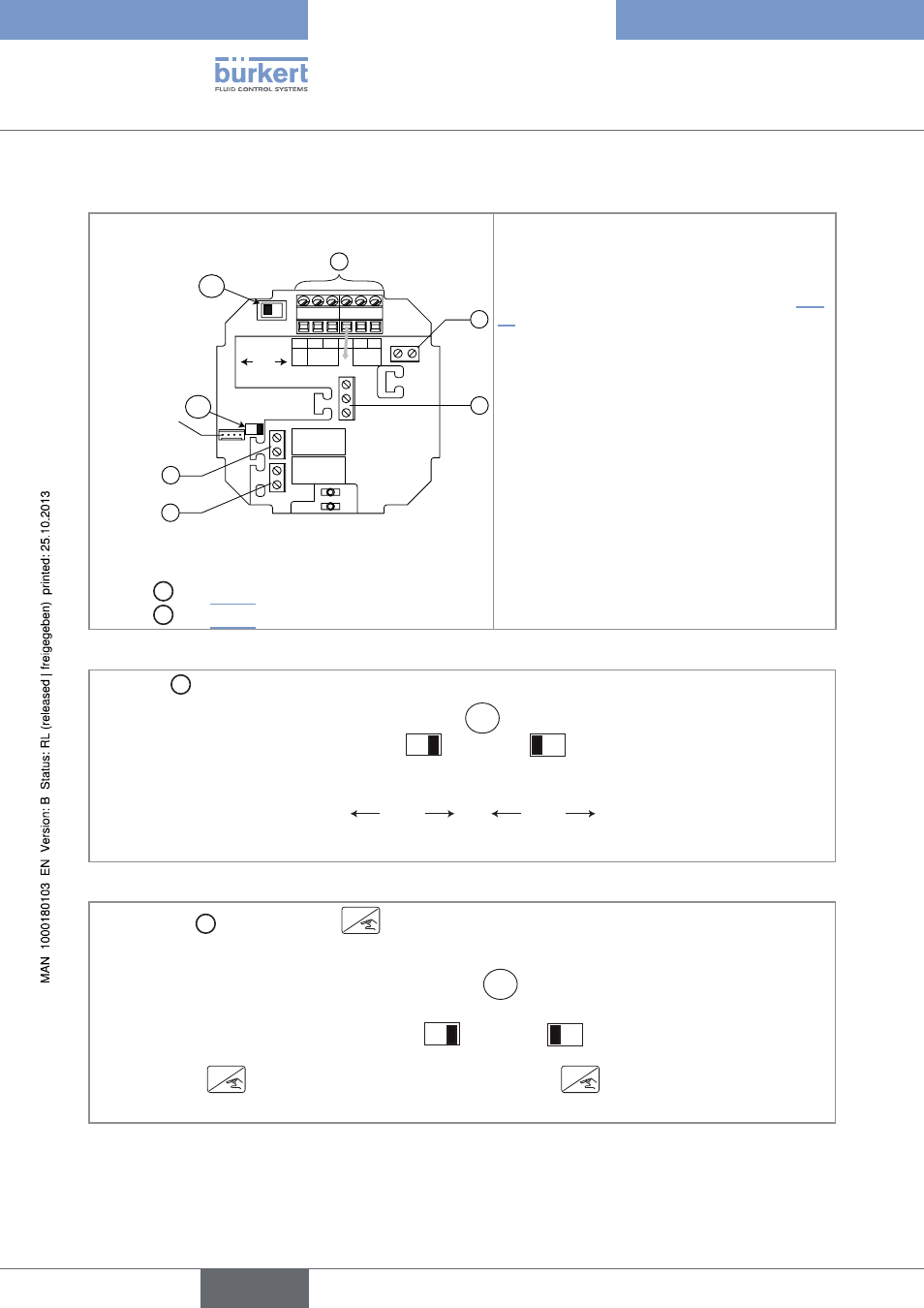
Terminal assignement and use of the selectors
4 pin ribbon ca-
ble coming from
the flow sensor
SOURCE
SINK
L+ L- PE P+ P-
Iout
Supply
18...36 Vdc
PULSE
DO1
CURRENT
PE
DI1
PE
DO2
DO3
AO1
+
-
OFF ON
2
B
1
4
5
3
A
Selector A : see Fig. 17
Selector B : see Fig. 18
terminal block 1
Iout: 4-20 mA output (AO1)
L+: V+ (positive voltage)
L-: 0V (power supply ground)
PE: functional earth, wired in the factory (see Fig.
19)
P+: positive transistor output (DO1)
P-: negative transistor output (DO1)
terminal block 2
PE: shieldings of both the power supply cable and
the AO1 and DO1 output cables
terminal block 3
PE: functional earth of the DI1 digital input
-: negative signal of the DI1 input
+: positive signal of the DI1 input
terminal block 4 wiring the DO2 relay output
terminal block 5 wiring the DO3 relay output
Fig. 16:
Terminal assignment
Use switch A to configure the wiring of the 4-20 mA current output in sinking or sourcing mode.
Wire the current output in sourcing mode.
Wire the current output in sinking mode.
A
SOURCE
SINK
CURRENT
SOURCE
SINK
CURRENT
Fig. 17:
Using the sink/source switch
Use the switch B to lock/unlock the
ENTER
key to prevent unauthorized access to the configuration of the
device.
The
ENTER
key is unlocked (default position).
The
ENTER
key is locked.
OFF ON
B
OFF ON
Fig. 18:
Using the EnTER key lock/unlock switch
English
Type 8045