Wiring the ao1 current output, Fig. 19, English – Burkert Type 8045 User Manual
Page 29
25
Installationandcommissioning
Earth cable coming from the housing.
On a version with stainless steel flow sensor, a second cable
is coming from the sensor.
1 2 3 4 5 6
Fig. 19:
Terminal block 1 connecting the earth wire coming from the housing (made in the factory)
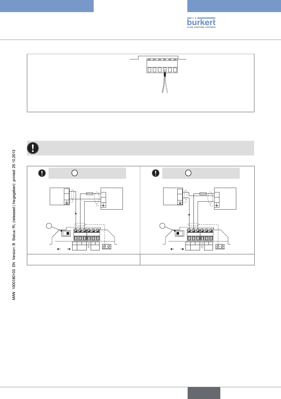
7.3.4.
Wiring the Ao1 current output
For safety reasons, secure the cables using a non-conducting cable clamp.
The 4-20 mA output can be wired in either sourcing or sinking mode.
Power supply
4-20mA input at external
device
Position the
A
switch to the right.
SOURCE
SINK
L+ L- PE P+ P-
Iout
Supply
18...36 Vdc
PULSE
DO1
CURRENT
PE
AO1
A
18-36 V DC
+
-
300 mA
I
+
-
(*)
SOURCE
SINK
L+ L- PE P+ P-
Iout
Supply
18...36 Vdc
PULSE
DO1
CURRENT
PE
AO1
A
18-36 V DC
+
-
300 mA
I
+
-
(*)
Power supply
4-20mA input at external
device
Position the
A
switch to the left.
Fig. 20:
Wiring of the 4-20 mA output (AO1) in
sourcing mode
Fig. 21:
Wiring of the 4-20 mA output (AO1) in sinking
mode
*) If a direct earth connection is not possible, fit a 100 nF/50 V capacitor between the negative power supply terminal and the
earth
English
Type 8045