Control card, English – Burkert Type 3004 User Manual
Page 16
16
Installation
Procedure:
→
Loosen left cable gland (pos.15, “Fig. 1” and “Fig. 2”) and feed
through the cable to be connected.
→
Connect cable according to the circuit diagram to the terminal strip
(pos. 14, “Fig. 1” and “Fig. 2”) of the power supply card (“Fig. 17”).
Connecting feedback
The limit switches for the feedback are suitable for a
maximum voltage of 250 V AC/DC – 5 A.
The rotary actuator features two limit switch contacts which are sup-
plied by the factory in an open position. These can be used for the
feedback of the rotary actuator.
The limit switch contacts are actuated via two cams
(pos. 13, “Fig. 1” and “Fig. 2”).
• The white cam is used to record the opening process (FC1).
• The black cam is used to record the closing process (FC2).
Procedure:
→
Connect cable to the terminal strip (pos. 12,
“Fig. 1” and “Fig. 2”) according to the schematic (“Fig. 17”).
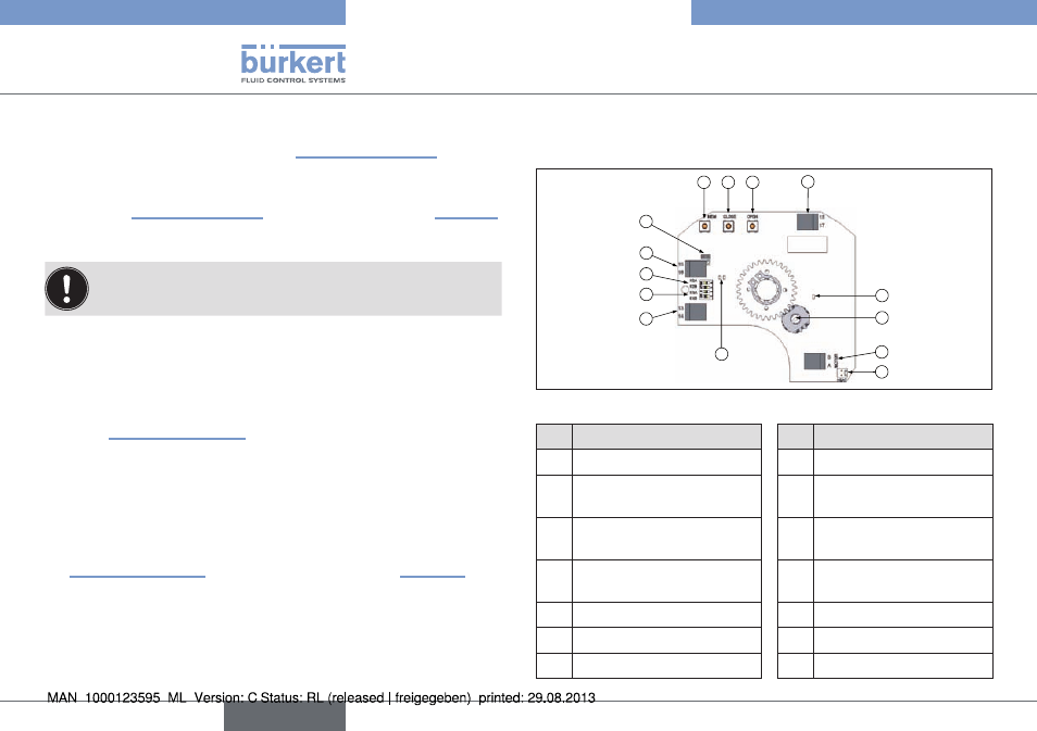
8.3. Control card
For rotary actuator with analogue control
H
G
D
E
C
F
N
B
I
A
M
L
K
J
Fig. 18: Control card (24V DC)
No.
Designation
No.
Designation
A
24 V DC power supply
H
K2 plug-in jumper
B
Connection terminals
transducer
I
K3 plug-in jumper
C
Connection terminals
feedback
J
Green and red LEDs
D
Adjusting button
K
Yellow LED: power supply
display
E
Adjusting button
L
Potentiometer
F
Adjusting button
M
Connection motor
G
K1 plug-in jumper
N
Connection heating resistor
english
Type 3004