English, Version with analogue signal, Type 3004 – Burkert Type 3004 User Manual
Page 15
15
Installation
Operating principle for Open / Closed mode (“Fig. 15”)
• Switch open = actuator closes
• Switch closed = actuator opens
Connecting feedback
The limit switches for the feedback are suitable for a
maximum voltage of 250 V AC/DC – 5 A.
The rotary actuator features two additional limit switch contacts which
are supplied by the factory in an open position. These can be used for
the feedback of the rotary actuator.
2
3
1
FC2
FC1
FCF
FC0
4-6
5
7
=
C
C
A
B
D
D
T/E
Power supply and control
Feedback
Motor
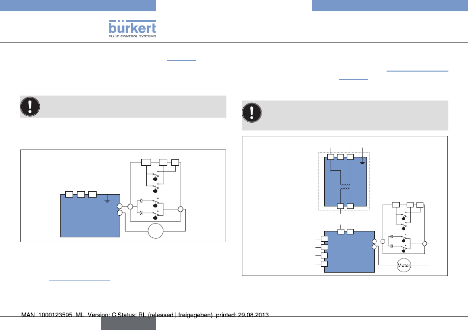
Fig. 16: Internal wiring of actuator
The limit switch contacts are actuated via two cams
(pos. 13, “Fig. 1” and “Fig. 2”).
• The white cam is used to record the opening process (FC1).
• The black cam is used to record the closing process (FC2).
Procedure:
→
Connect cable to the terminal strip (pos.12, “Fig. 1” and “Fig. 2”)
according to the schematic (“Fig. 16”).
8.2.3. Version with analogue signal
The power supply voltage of the actuator is 15-30 V AC
(12-48 V DC) or 100-240 V AC (100-350 V DC).
Always observe the specifications on the rating plate!
T/E
FC2
FC1
FCF
FC0
4-6
5
7
=
C
B
D
D
A
C
2
17
18
18
17
N
-
Ph
+
N
-
Ph
+
3
1
16
15
14
13
+
-
-
+
Power supply
100-240 V AC
(120-350 V DC)
or
15-30 V AC
(12-48 V DC)
Feedback
0
-2
0 m
A / 4
-2
0 m
A / 0
-1
0 V
Input
Power supply
24 V DC
Feedback
Fig. 17: Circuit diagram
english
Type 3004