Connection of the air inlet and exhaust lines, Connection of the pressure supply, Connection of the exhaust air – Burkert Type 8650 User Manual
Page 73: Pilot exhaust air / auxiliary control air, Connection.of.the.air.inlet.and.exhaust.lines, . connection.of.the.pressure.supply, . connection.of.the.exhaust.air, . pilot.exhaust.air./.auxiliary.control.air
73
10.
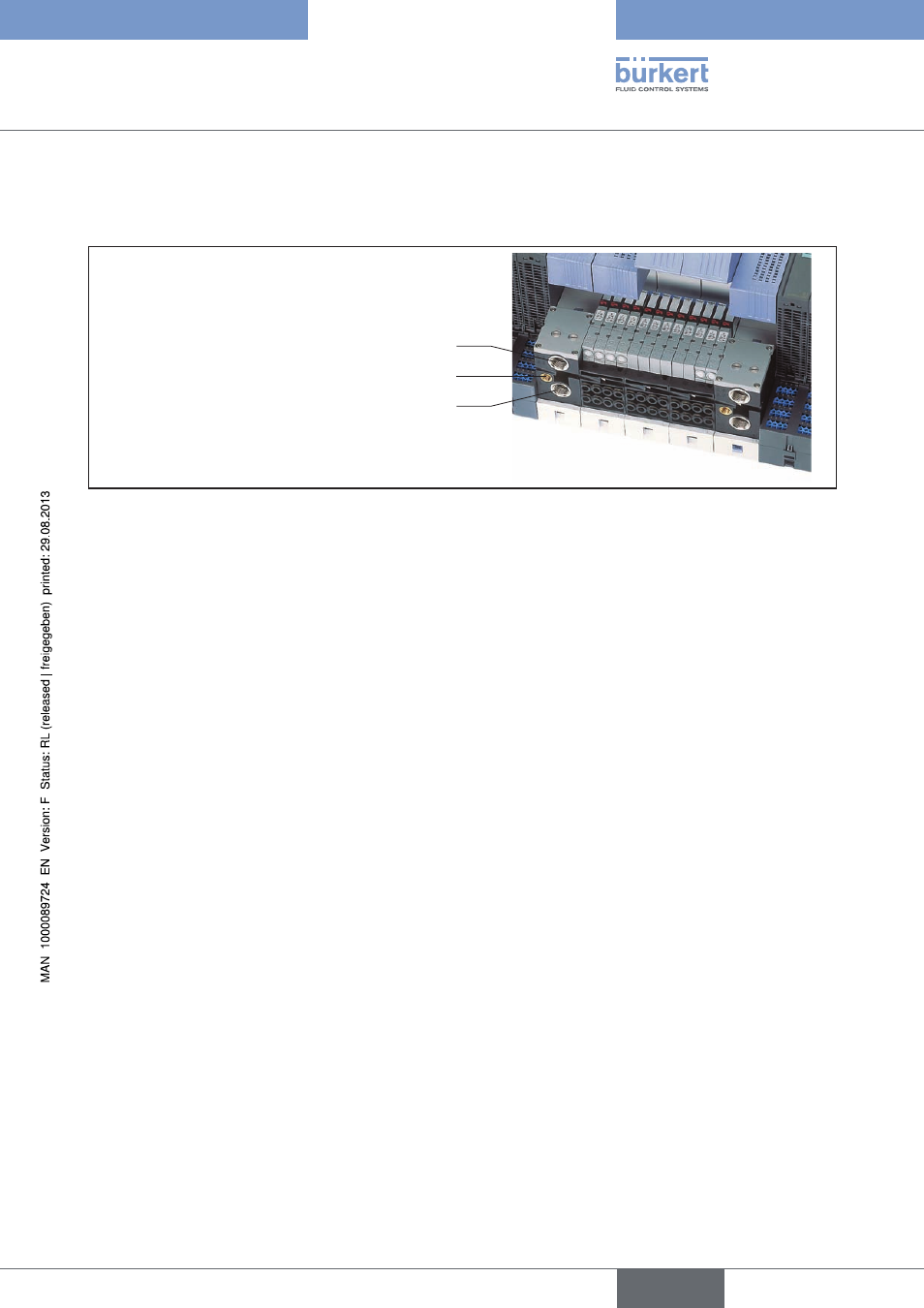
CONNECTION OF THE AIR INLET AND
EXHAUST LINES
Exhaust air
Pilot exhaust air / auxiliary control air
Compressed air supply
Fig. 15: Connections of the air inlet and exhaust lines
10.1. Connection of the Pressure Supply
→
Connect the compressed air supply to the P/1 connections on the connection modules.
DThe supply should be fed via the largest possible lines to prevent pressure drops.
In larger AirLINE Ex systems and high-consumption applications the supply should be connected for the right
and left supply segment, optionally also via additional supply segments in the middle
→
Seal the unused P/1 connections with a plug.
10.2. Connection of the Exhaust Air
→
Connect the exhaust air to the R/S 3/5 connections on the connection modules.
The exhaust air should be conveyed along the largest possible lines and, if required, via silencers at high flow
rates in order to prevent back pressures.
The exhaust air should be connected for the right and left supply segment, optionally also via additional supply
segments in the middle.
10.3. Pilot Exhaust Air / Auxiliary Control Air
Depending on which valves you operate on the AirLINE Ex system, port X is used as follows:
10.3.1. Standard Valves
In this case the exhaust air from the pilot control valves is exhaust separately from the R/S 3/5 port to port X. This
avoids problems in the event that higher back-pressures occur in the R/S 3/5 channel.
This should be done using the largest possible lines if necessary with mufflers for high flow rates in order to avoid
back-pressure.
Type 8650
english
Installation