Burkert Type 8686 User Manual
Page 35
35
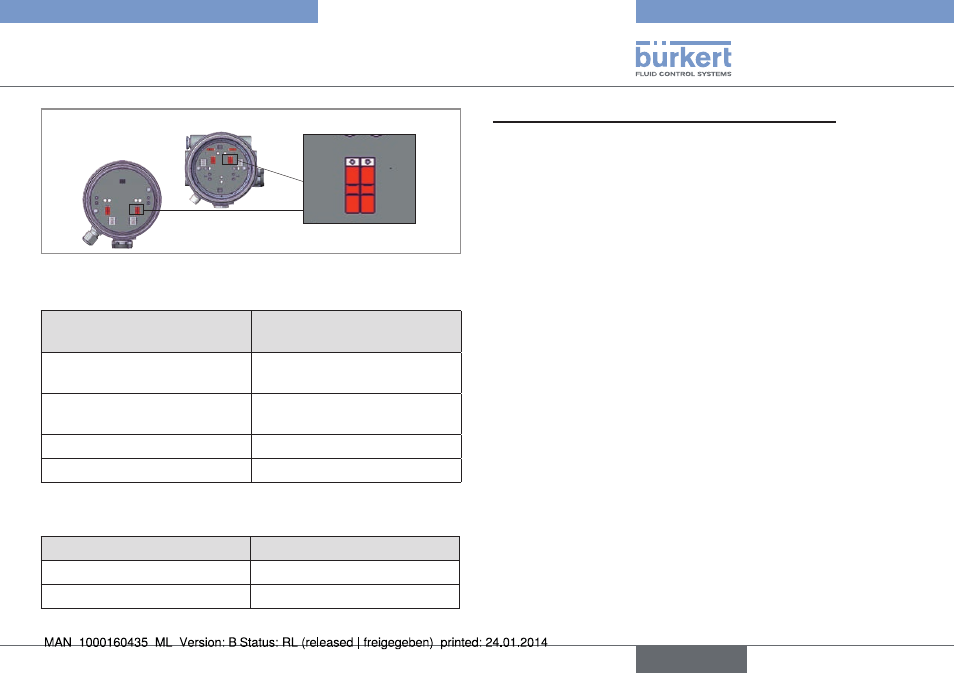
Controlanddisplay
Bot
gn ye
Bot
To
p
To
p
Typ 8685
Typ 8686
Fig. 29: Color assignment of end positions via slide switch
Refer to the PCB labeling in the table below
switch position for one
actuator side
actuator status led
Both switches up
End position Top yellow /
End position Bot green
Both switches down
End position Top green /
End position Bot yellow
Switch up/down
- Invalid state -
Switch down/up
- Invalid state -
Tab. 13: Color assignment of end positions
The following function is set in the factory:
color
actuator status
Green LED lit
Lower end position
Yellow LED lit
Upper end position
Tab. 14: Assignment of status of actuator LEDs (end position)
step 3: reference movement for spindle adjustment
To make the fine adjustment of the spindle for actuator size, it is essential
to move both spindles from the lower to the top end position.
procedure for type 8685:
Actuator with design control function A (CFA, NC):
→
Under maximum control pressure, move the spindles up by acti-
vating the actuator chambers.
→
After the end position is reached (preselected LED is lit), turn off
the control pressure. The spindle moves to the lower end position.
LED for end position Bot is lit with the selected color.
Actuator with design control function B (CFB, NO):
→
Under maximum control pressure, move the spindles down by
activating the actuator chambers.
→
After the end position is reached (preselected LED is lit), turn
off the control pressure. The spindle moves to the upper end
position. The corresponding LED for the end position is lit with
the selected color.
English
Type 8685 / 8686