Burkert Type 8686 User Manual
Page 15
15
Assembly
designation
Order no.
Adapter set for Type 8685
684267
Adapter set for Type 8686
684268
Tab. 2: Adapter sets
procedure:
step 1: assembly of adaptation body on the actuator
→
Unscrew the transparent cap from the actuator.
→
Place the 52 x 3 O-ring in the profile on the bottom of the adap-
tation body.
→
Place the adaptation body on the actuator, paying close attention
to the coding pin.
→
Screw the adaptation body tightly onto the actuator with two
cylinder screws M6 x 12.
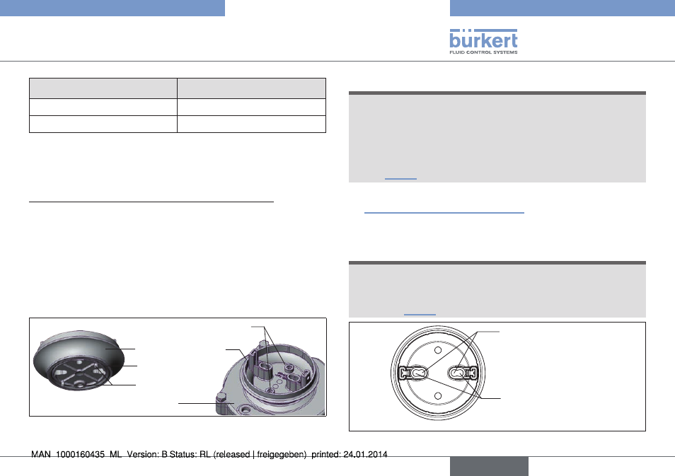
O-ring 52 x 3
Adaptation body
Coding pin
Cylinder screws M6 x 12
Actuator
Fig. 6: Assembly of adaptation body
note!
using a switch spindle that does not fit will result in irrepa-
rable destruction of the feedback head and/or control head
and the actuator.
▶ Use only switch spindles that match the actuator size. The cor-
responding actuator size identification (RV50, RV70, RV110)
for switch spindles are embossed on the front of the PVC cap
(see “Fig. 5”).
→
Select the switch spindle that matches the actuator size (see
“Fig. 5: Switch spindle identification”).
→
Wet the thread of two switch spindles that match the actuator
size with Loctite screw locking M290.
note!
using the wrong spindle lead-through will result in
malfunction.
▶ Use only the spindle lead-through that matches the actuator
size (see “Fig. 7”).
Spindle lead-through
for actuator size
RV50
Spindle lead-through
for actuator sizes
RV70 and RV110
Fig. 7: Spindle lead-through
English
Type 8685 / 8686