Burkert Type 8686 User Manual
Page 17
17
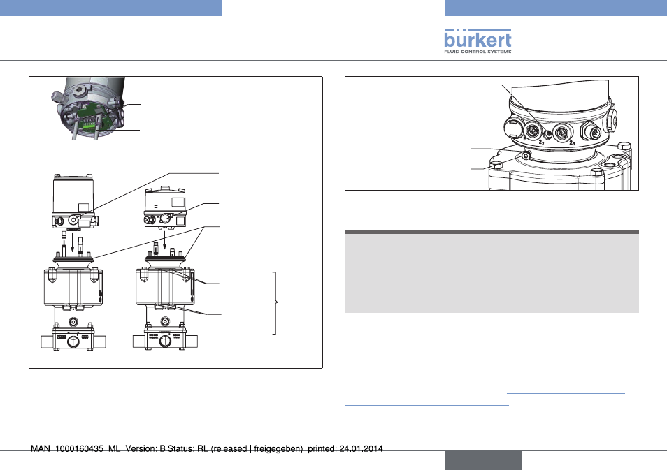
Assembly
Form seal
Dummy plug
Pressure-relief valve
Connection
SFB
Connection
SFA
Type 2036
Type 8686
Type 8685
Pneumatic actuator
connections
Switch spindle
Recess
Fig. 9: Assembly of feedback head / control head
→
Push the feedback head / control head onto the adaptation body
until no gap is visible on the form seal. Now align the mounting hole
of the feedback head / control head on each side with the square
nut of the adaptation body.
Fastening screw M4
Mounting hole of the
feedback head / control
head concentric with
square nut of the adap-
tation body
O-ring 3.5 x 1.5
Fig. 10: Fastening of feedback head / control head
note!
if the torque is too high when screwing in the fastening screw
or if the O-ring is missing, degree of protection ip65 / ip67 is
not ensured.
▶ The fastening screw may only be tightened to a maximum torque
of 0.5 Nm ± 0.1 Nm.
▶ Check the position of the O-ring.
→
Use the two fastening screws M4 and matching O-rings to
fasten the feedback head / control head onto the adaptation
body (torque: 0.5 Nm ± 0.1 Nm).
The mechanical connection is already completed for the feedback
head after these two assembly steps. “Step 3: Assembly of pneu-
matic connection - install the actuator” must still be performed for
the control head.
English
Type 8685 / 8686