Figure 4-14, Figure 4-13 – Atec Tektronix-1502 User Manual
Page 55
TM 9-4935-601-14-3&P
Adjustment Procedure
114.
Move the test lead from R2229 to
R2326 (see Fig. 4-13). The DVM should read
0.400 0.008 volt.
115.
Move the test lead from R2326 to
R2325 (see Fig. 4-13). The DVM should read
0.199 0.004 volt.
116.
Move the test lead from R2325 to
R2323 (see Fig. 4-13). The DVM should read
0.0991 ±0.002 volt.
117.
Move the test lead from R2323 to
R2322 (see Fig. 4-13). The DVM should read
0.0405 0.0008 volt.
118.
Move the test lead from R2322 to
R2321 (see Fig. 4-13). The DVM should read
0.0200 ±0.0004 volt.
119.
Move the test lead from R2321 to
R2228 (see Fig. 4-13). The DVM should read
0.0100 ±0.0002 volt.
120.
Remove the test leads from the 1502
and turn the ZERO REF control fully
counterclockwise. If R1659 (DC BAL) was adjusted
during step 113, repeat steps 104 through 107.
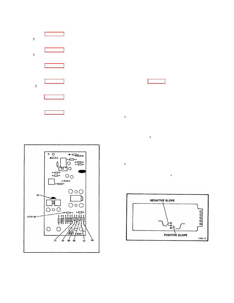
Figure 4-13. Vertical AMP/Slow Ramp Board.
X-Y OUTPUT MODULE CHECKS AND
ADJUSTMENTS
Pen Lift Signal
1.
Set the Digital Multimeter
RANGE/FUNCTION control to 20 on the DC
VOLTS scale.
2.
Turn the 1502 upright.
3.
Place the terminal connection link of the
OUTPUT MODULE board on the negative slope
terminals (see Fig. 4-14).
4.
Connect the lead from the DVM HI terminal
to the X- Y OUTPUT MODULE PEN LIFT red
terminal and the lead from the DVM LO terminal to
the X-Y OUTPUT MODULE PEN LIFT black
terminal.
5.
Check-that the DVM shows approximately
5 volts.
6.
Momentarily push the RECORD switch to
RECORD, then release the switch. Check that the
voltage goes to +0.5 volt or less and returns to
approximately 5 volts at the end of the sweep.
7.
Move the terminal connection link to the
positive slope terminals on the X-Y OUTPUT
MODULE board.
8.
Check-that the DVM reads approximately
0.5 V. volt.
9.
Push the RECORD switch to RECORD and
check that the DVM reads 4 volts or greater, then
returns to approximately 0.5 volt at the end of the
sweep.
Figure 4-14. Output Module Connection Link.
REV B JUL 1980
4-17