Figure 4-4 – Atec Tektronix-1502 User Manual
Page 43
TM 9-4935-601-14-3&P
Performance Check
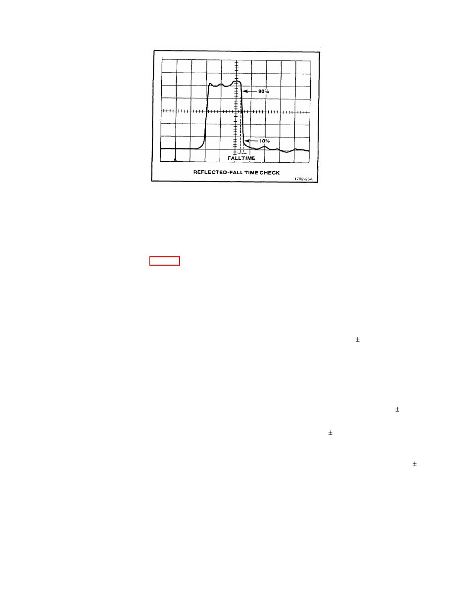
Figure 4-4. Falltime.
32. Connect the probe adapter to the CABLE connector if the connector is the grounding type (grounded
CABLE connector used SN B040616 and up). Preset the POSITION and GAIN controls so the trace is on
screen and the amplitude is approximately 4 divisions. Adjust the FOCUS and INTENSITY controls for a clear
bright trace.
33. Adjust the GAIN control so that the total amplitude of the display is exactly 4 divisions. (If unable to
adjust the GAIN control properly, check the Gain Amplifier or Vertical Amplifier circuits.)
34. Change the METRES/DIV control to .5 and the MULTIPLIER control to X.1.
35. Turn the ZERO REF SET control counterclockwise to locate the pulse at center screen. Check for
correct waveform as shown in Fig. 4-1c. (If display is not correct, check the sampling circuitry, avalanche and
Snap-off adjustments.)
36. Remove the probe adapter and connect the precision 50
Ω
terminator (Tektronix Part No. 011-0123-00)
to the CABLE connector. Turn the GAIN control fully counterclockwise and note the amplitude of the pulse.
Turn the GAIN control fully clockwise; the amplitude should be 3.5 times greater than the amplitude with the
GAIN control counterclockwise. (Adjust the POSITION control as necessary.)
37. Set the mp/DIV control to 200, the METRES/DIV control to 5, and the MULTIPLIER control to X.1.
38. Adjust the ZERO REF SET control so that the pulse is at the center of the screen. Adjust the GAIN
control for exactly 5 divisions of amplitude.
39. Remove the 50
Ω
terminator and connect the probe adapter to the CABLE connector (SN B040616 and
up). Change the mp/DIV control to 500. The amplitude of the pulse must be 4 divisions 0.12 divisions (±0.6
minor division). If not, the Vertical Amplifier circuit or Sampling circuit should be checked.
40. Set the METRES/DIV control to .25 and adjust the ZERO REF SET control so the leading edge of the
incident pulse is set on the vertical centerline.
41. Change the MULTIPLIER control to X.1. The leading edge of the incident pulse must be within 1
division of the vertical centerline. (If not, check the X.1 Position calibration (R1 132), the Sampler Comparator,
or the Pulser Comparator.)
42. Attach the precision 50
Ω
cable (Tektronix Part No. 012-0482-00) to the CABLE connector and change
the MULTIPLIER control to X1. Adjust the ZERO REF SET control to locate the incident pulse on the graticule
reference line. The reflected pulse should be 3.66 divisions to the right of the incident pulse ( 1 minor
division).
43. Change the MULTIPLIER control to X.1 and adjust the DISTANCE dial until the reflected pulse is
located on the graticule reference line. The DISTANCE dial should read 009.2 1.0 digit. Press the ZERO
REF CHECK button; the incident pulse should return to the graticule reference line. If the incident pulse does
not return to the graticule reference line, adjust the ZERO REF SET control so that the incident pulse is located
on the graticule reference line. Release the ZERO REF CHECK button and check that the reflected pulse is
located on the graticule reference line (adjust the DISTANCE dial if necessary; it must remain at 009.2 1.0
digit). If the DISTANCE dial reading is incorrect or the ZERO REF CHECK control does not work properly,
check Distance Offset, Fast Ramp, and Pulser Comparator circuitry. Return the DISTANCE dial to 000.
NOTE
To more accurately check the DISTANCE dial, a known length of Solid
Polyethylene (V
P
= 0.66) cable (up to 1500 feet) should be used.
44. Change the METRES/DIV control to 5, the MULTIPLIER control to X1 and the mp/DIV control to 200.
Adjust the ZERO REF SET control so that the reflected pulse is located exactly on the 8th graticule line from
the left-hand edge of the graticule.
REV B FEB 1980
4-5