Figure 2-8, Figure 2-9 – Atec Tektronix-1502 User Manual
Page 23
TM 9-4935-601-14-3&P
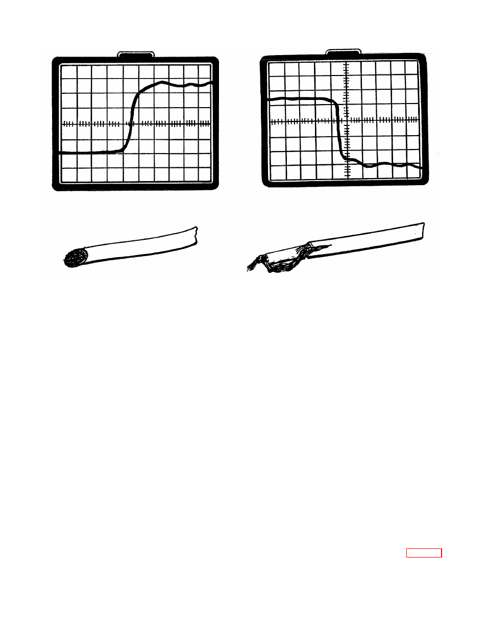
Figure 2-8. Open Cable.
Figure 2-9. Shorted Cable.
CHECKING CABLES WITH IMPEDANCE OTHER THAN 50
Ω
Cables with a characteristic impedance other than 50
Ω
can be evaluated by adjusting the GAIN control
(screwdriver adjust) to correct the reflected pulse for +1p at the open end of a cable. When the GAIN is
changed, the incident pulse will no longer be 1p.
To reset the GAIN for an impedance other than 50
Ω
, either connect an impedance-matching adapter (50
to 75
Ω
, 50 to 93
Ω
, 50 to 125
Ω
, etc) to the CABLE connector and connect a short length of cable (with
impedance the same as the adapter, i.e., 75
Ω
, 93
Ω
, 125
Ω
, etc.) to the adapter or connect the cable to be
tested to the CABLE connector. With the mp/DIV control set at 500, position the trace on the graticule so that
the display of the cable appears in the display. Now adjust the GAIN control so that the open end display
(reflected pulse) is set 2 divisions above the cable display (horizontal centerline). This sets the reflected pulse
to +1p from the characteristic impedance.
NOTE
If an impedance adapter is not used, secondary reflections will re-appear as discontinuities
beyond the open end of the cable.
1502 ACCESSORIES
Plug-Ins
The 1502 plug-in compartment will accept the X-Y OUTPUT MODULE (provided as a standard accessory) or
the TEKTRONIX Y-T Chart Recorder (part number 016-0506-03).
Using an X-Y Recorder
The X-Y OUTPUT MODULE is wired for either a positive or negative pen lift signal. Before using the X-Y
OUTPUT MODULE, be sure that the pen lift circuit on the etched circuit board is properly connected. Fig. 2-12
shows the proper connection for either a positive or negative pen lift signal.
REV B FEB 1980
2-8