Figure 4-7, Figure 4-8 – Atec Tektronix-1502 User Manual
Page 48
TM 9-4935-601-14-3&P
Adjustment Procedure
Turn the instrument POWER off. Turn the instrument upside down and remove the shield that covers the
pulser/sampler circuitry (remove 12 screws). Remove U1575 from its socket. In the following steps,
instructions are given on how to provide an external trigger to the 1502 (see Fig. 4-6).
44. Set the 1502 controls as follows:
mp/DIV
200
FEET/DIV
100 @ X1
DIELECTRIC
AIR (all buttons out)
DISTANCE
000
Duration
50,
µ
s
Variable Duration
Fully ccw
Period
Ext Trig
Low Level
-1.5
High Level
2.0
Back Term
Pull Out
All pushbuttons
Out
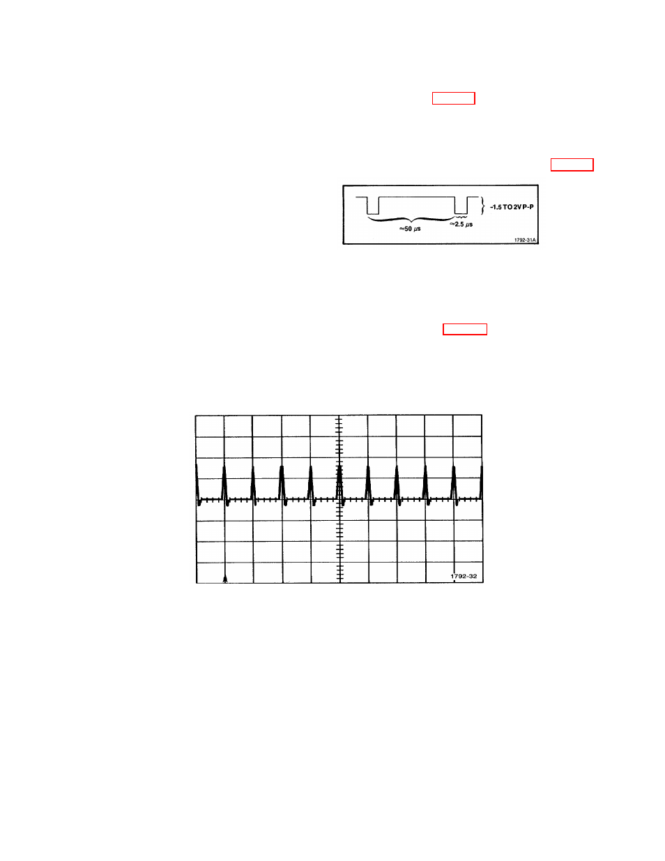
Figure 4-7. Pulse Generator Output
.
46. Set the TG 501 Time Mark Generator for 0.2
µ
s time marks. Connect a 1X probe from the PG 502
Output to the Red test point located near U1575. Turn the instrument POWER on.
NOTE
The time marks must not exceed 0.85 V to keep the tunnel
diode in the low state.
47 (a). Obtain a waveform on the 1502 crt similar to the one shown in Fig. 4-8. Use the variable pulse
amplitude control of the PG 502 and the DISTANCE control of the 1502 to align the second time mark with the
second graticule line.
NOTE
If the instrument is to be used with the optional chart recorder,
continue with the remainder of this step. If the instrument is not
to be used with- a chart recorder, proceed with step 48.
Figure 4-8. Time Marks Aligned (Standard).
(b). Check that the chart paper in the recorder has a bold line next to the hole in the paper that shows a
red line through the hole. If the red line is not aligned with a bold line on the chart paper, pull enough chart
paper through the recorder to line them up.
(c). Press the RECORD switch to obtain a recording of the time marks. The recording should show the
same timing as seen on the crt between the second and tenth graticule lines ±2%.
(d). Adjust-R3213 (H POS) and R3217 (HORIZ GAIN), located on the OUTPUT AMPS board, to match
the timing and position of the time marks on the crt to the chart recording.
48 (a). Adjust-R1435 (FT/DIV CAL) so the eleventh time mark is 0.2 division to the left of the eleventh
graticule line. Keep the first time mark aligned with the first graticule line with the DISTANCE control.
(b). Set the FEET/DIV control to 50, set the TG 501 to .1 ps and check that when the first time mark is
aligned with the first graticule line, the eleventh time mark is 0 to 0.4 division to the left of the eleventh graticule
line.
(c). Set the FEET/DIV to 20, set the TG 501 to 50 ns and check that when the first time mark is aligned
with the first graticule line, the ninth time mark is O to 0.4 division to the left of the eleventh graticule line.
(d). Set the FEET/DIV to 10, set the TG 501 to 20 ns and check that when the first time mark is aligned
with the first graticule line, the eleventh time mark is 0 to 0.4 division to the left of the eleventh graticule line.
REV B FEB 1980
4-10