Figure 3-4 – Atec Tektronix-1502 User Manual
Page 30
TM 9-4935-601-14-3&P
During time slots 1 and 2,Q1597 is saturated, discharging memory capacitor C1596. At the start of time
slot 3, Q1597 is cut off, allowing the current through CR1691 and R1691 to charge C1596 via R1692 and
R1594. (C1596, R1692, and R1594 compose the memory circuit). This causes the gate voltage of Q1693 to
be stepped up to a value determined by voltage divider R1691, R1692, and R1594 and then increase with a
time constant rate determined by R1691, R1692, R1594, and C1596 (see Fig. 3-3g).
A current with a waveform similar to the voltage waveform at the gate of Q1693 will flow through R1693
and is added to the idle current from R1601. This current flows through Q1603 to output tunnel diode CR1703,
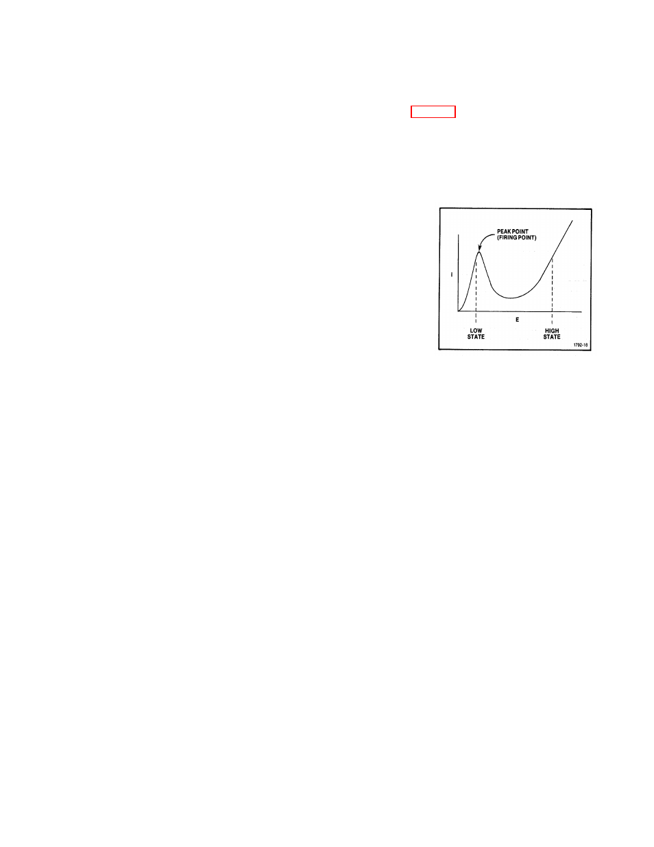
and continues to increase until the tunnel diode goes into the high voltage state. At this point, comparator
Q1695 and Q1688 cause Q1683 to remove the memory charge current. Thus, current stops flowing into
C1596, causing the voltage ramp at the gate of Q1693 to stop and step-down. Similarly, the current ramp into
the tunnel diode will stop and step-down.
The comparator consists of Q1695 and Q1688. Its reference is set at
a negative level, except during time slot 3 when it is set at a positive 300
mV. The reference input voltage (the voltage at the base of Q1695) equals
the tunnel diode voltage (which is always above ground level). These
conditions cause Q1683 to saturate and remove the memory charging
current. At the beginning of time slot 3, when the tunnel diode is still at its
low voltage state, the comparison voltage is set at 300 mV. At this level
Q1683 is not conducting, therefore, the memory charge current flows to the
memory capacitor. When the tunnel diode fires, the comparator input
voltage goes above the 300 mV comparison level. Q1683 becomes
saturated again and the memory charge current is removed. The
comparison reference levels are set by R1682, R1683, R1681, and Q1675.
Factory selectable resistors R1702 and R1707, along with capacitors C1701
and C1706, are used to compensate for tunnel diode thermal time
constants.
Figure 3-4. Tunnel Diode Voltage-
Current Curve.
A tunnel diode, CR1609, is used to reduce jitter on the output step pulse. Q1608 conducts when TD
TRIGGER is received from the pulser comparator during time slot 6. The current through Q1608 causes tunnel
diode CR1609 to go to the high voltage state, producing a fast spike pulse through C1609 and R1701 to tunnel
diode CR1703. This fires CR1703, sending the test pulse to the CABLE connector. Dc balance network,
R1753, R1659, and C1655 provides an output of "zero" level when no test pulse is being generated, and if the
CABLE terminations are not too extreme.
Sampler
The Sampler circuitry provides positive and negative strobes to strobe the sampling diodes, so that
during a short time period (100 ps), a sample of the incident pulse or reflected signals can be taken. The
sampling preamplifier amplifies these signals for display on the crt. The sampler consists of a Sampling Gate,
Sampling Preamplifier, Strobe Generator, and Blowby Compensation.
Sampling Gate. Dual-diode Sampling Gate, CR1732, allows signals from the output terminal to appear
at the preamplifier input for a short period of time. The bandwidth (or risetime) of the sampler is proportional to
the conduction time of the diodes, which are controlled by the strobe width of the strobe generator.
Sampling Preamplifier. The Sampling Preamplifier consists of Q1648, Q1556, and Q1643. While
strobing is occurring, a signal sample is taken from the transmission line and stored in capacitors C1635,
C1636, C1637, C1638, C1646, and C1647. The preamplifier amplifies the charge stored in the capacitors. A
positive feedback is provided by C1646 and C1647 to bring the sampling efficiency to unity. The sampling
efficiency is adjustable by R1543.
The preamplifier has a gain of approximately 2 times, which is controlled by R1549 and R1651. R1639
and R1630 are needed to bleed off some of the reverse self-charge of C1637 and C1638. This allows the
sampling gate to conduct during the peak amplitude of the strobes and thus determines the sampling aperature.
Strobe Generator. The Strobe Generator consists of preamplifier Q1553; signal-shaping amplifier
Q1544 and Q1535; avalanche circuit Q1537; snap-off diode circuitry and strobe shaper, CR1632; and shorted
strip lines.
REV A FEB 1980
3-5