E8361a – Atec Agilent-E8361A User Manual
Page 29
9
E8361A
Corrected system performance with 2.4 mm connectors
Description
Specification (dB)
10 to 200 MHz
1
200 MHz to 2 GHz
2 to 20 GHz
20 to 40 GHz
40 to 50 GHz
Directivity
55
9
1
Source match
5
6
5
0
Load match
1
7
6
Reflection tracking
±0.050 (+0.0/°C)
±0.00 (+0.0/°C)
±0.00 (+0.0/°C)
±0.060 (+0.0/°C)
±0.080 (+0.0/°C)
Transmission tracking
±0.100 (+0.0/°C)
±0.059 (+0.0/°C)
±0.079 (+0.0/°C)
±0.110 (+0.0/°C)
±0.15 (+0.0/°C)
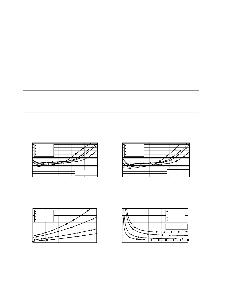
Transmission uncertainty (specifications)
Reflection uncertainty (specifications)
Magnitude
0.01
0.1
1
10
-90
-80
-70
-60
-50
-0
-0
-0
-10
0
10
Transmission coefficient (dB)
E861A full two port cal using N69A
00 MHz to GHz
to 0 GHz
0 to 0 GHz
0 to 50 GHz
S11 = S = 0
Source power = -15 dBm
Un
ce
rta
in
ty
(d
B)
Phase
0.1
1
10
100
-90
-80
-70
-60
-50
-0
-0
-0
-10
0
10
Transmission coefficient (dB)
E861A full two port cal using N69A
00 MHz to GHz
to 0 GHz
0 to 0 GHz
0 to 50 GHz
S11 = S = 0
Source power = -15 dBm
Un
ce
rta
in
ty
(d
eg
re
es
)
Magnitude
0
0.01
0.0
0.0
0.0
0.05
0
0.
0.
0.6
0.8
1
Reflection coefficient (linear)
E861A with N69A
00 MHz to GHz
to 0 GHz
0 to 0 GHz
0 to 50 GHz
S1 = S1 = 0
Source power = -15 dBm
Un
ce
rta
in
ty
(l
in
ea
r)
Phase
0
6
8
10
0
0.
0.
0.6
0.8
1
Reflection coefficient (linear)
E861A with N69A
00 MHz to GHz
to 0 GHz
0 to 0 GHz
0 to 50 GHz
S1 = S1 = 0
Source power = -15 dBm
Un
ce
rta
in
ty
(d
eg
re
es
)
Standard configuration and standard power range (E8361A)
Applies to E8361A PNA Series analyzer, N4693A
(2.4 mm) ECal electronic calibration module, 85133F
flexible test port cable set, and a full two-port
calibration. (Specifications apply over environmental
temperature of 23 °C ±3 °C, with less than 1 °C
deviation from calibration temperature.)
1. Typical performance.
1. Configurable Test Set, Extended Power Range and Bias-Tees, Receiver Attenuators, Frequency Offset Mode,
and Reference Channel Transfer Switch (Option 01, UNL, 016, 080 and 081).