0 operation, 1 start-up and test – Alpha Technologies XM2, XM2-HV, XM2-HP User Manual
Page 53
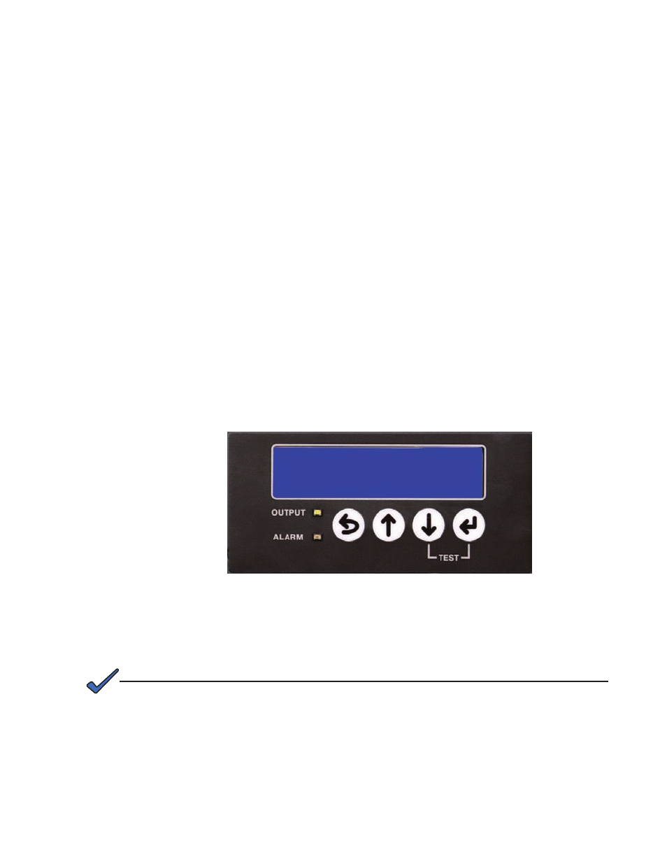
Fig. 4-1, Configuration Screen
4.0 Operation
4.1 Start-up and Test
4.1.1 AC Line Operation
1. Before making power supply connections, verify the correct voltage and
frequency are available from the AC utility power source and voltage and
polarity from the DC battery system.
2.
Verify the AC circuit breaker (on the customer supplied service disconnect) and
the battery breaker on the power supply are off.
3. Plug the power cord into the convenience outlet and the battery cable into the
inverter module. Plug the RTS into the temp probe connection and attach it to
the center battery. Refer to Fig. 1-9. At this time, if an LRI is installed, connect it
to the front panel connector labeled LRI.
4.
Switch the AC (service disconnect) circuit breaker on to start initial power
up. During this stage the power supply performs a “display test” and verifies
configuration for the power supply. After the initial display test, a “No Batteries”
alarm message appears in the Smart Display because the battery breaker is
off. The green output LED remains off and the red alarm LED continues to flash
while in this alarm state.
Access the configuration screen any time by simultaneously pressing UP and ENTER.
NOTE:
i2M OUT
FREQ
BAT IN
90V 15A 60Hz
36V 120
53
017-805-B0-010 Rev. K2