Alpha Technologies XM2, XM2-HV, XM2-HP User Manual
Page 27
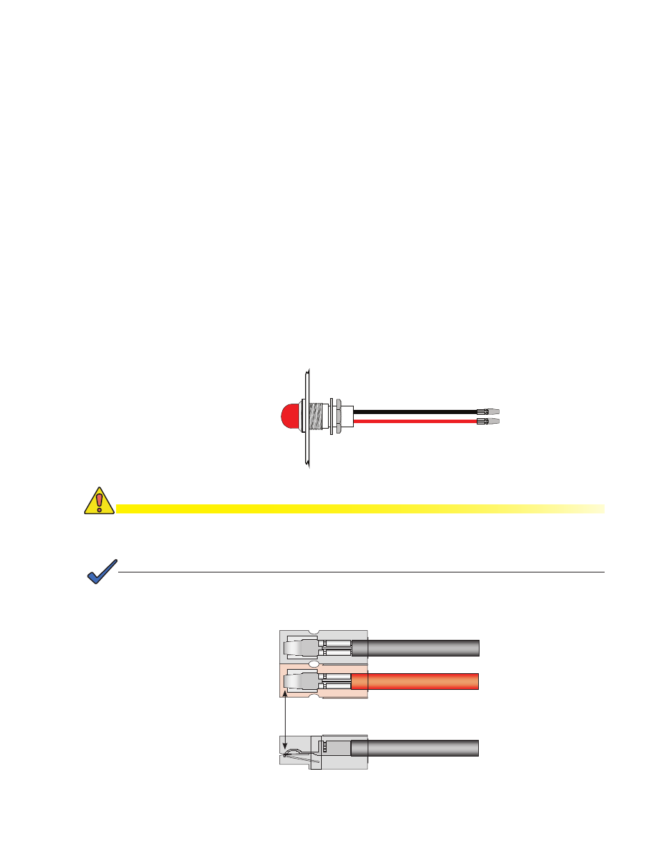
Fig. 2-3, Local/Remote Indicator Lamp
Secure the contact. If you do not properly position the contact, overheating and cable
assembly failure can result.
NOTE:
CAUTION!
Top View
Black Wire
Side View
Red Wire
To remove the wire from the plastic housing, use a small screwdriver to depress the metal retainer
and slide out the wire.
Fig. 2-4, Wire/Housing Assembly
2.2
Installing the Optional Indicator Lamps, continued
2.2.2 Local/Remote Indicator
The Local/Remote indicator (Red lamp) is located on the outside of the enclosure.
During normal AC operation, the lamp remains OFF. The lamp comes ON only when
the power supply is running in Standby Mode. In the event a major alarm is detected,
the lamp flashes to indicate service is required. The LRI is a simple form of status
monitoring which allows the operational status of the power supply to be verified from
the ground.
Installation Procedure:
1.
Remove the front-most knockout (see Fig. 2-5).
2. Feed LRI wires through the hole.
3.
Slide locking nut over the wires and thread onto lamp body (see Fig. 2-3).
4. Insert the crimped contacts into the plastic connectors. The BLACK wire must
always go into the BLACK housing and the RED wire into the RED housing (see
Fig. 2-4).
5. Connect the wire harness into the LRI connector on the front panel of the power
supply.
Red Housing
Black Housing
Verify contact snaps
over metal retainer
27
017-805-B0-010 Rev. K2