Intelligent cableups layout, Escape up down enter – Alpha Technologies XM2, XM2-HV, XM2-HP User Manual
Page 20
Always verify proper polarity of cables before connecting the batteries to the power module.
Reversing the battery polarity can cause permanent damage to the power supply. Polarity is
clearly marked for easy identification.
NOTE:
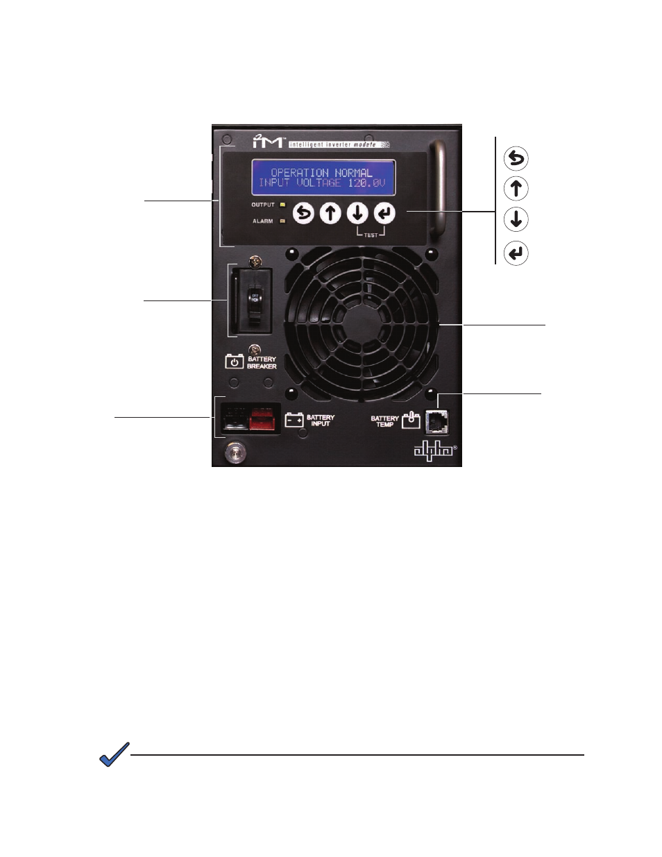
Fig. 1-7, Inverter Module Connections
Smart Display
Escape
Up
Down
Enter
1.2
Intelligent CableUPS Layout
, continued
1.2.2
Inverter Module Overview, continued
Smart Display: All operational functions, system testing, setup items and alarms are avail-
able via the Smart Display panel on the front of the power supply
(the Smart Display is
covered in detail in Section 4.2). Display functions are accessible by pressing any of the
four keys: ESCAPE, UP, DOWN or ENTER. Backlighting is activated when any of the four
keys are pressed and stays lit for a period of one hour. There are four levels of menu items
for the standard unit: Operation Normal, Additional Information, Setup and Alarms. For units
equipped with DSM2 (or newer) Communications Modules the four levels are: Operation
Normal, Communication Information, Setup and Alarms. Pressing ENTER will sequence the
display one level lower and pressing ESCAPE will sequence the display one level higher.
Battery Breaker:
The battery breaker disconnects the batteries from the inverter module’s
DC circuit. With the battery breaker turned off, the power supply does not transfer to standby
mode, the inverter is disabled and the battery charger cannot charge the batteries. The
breaker trips when an overcurrent is detected in the DC circuitry or the battery polarity is
accidently reversed.
Battery Input Connector: The battery cable connector plugs directly into the inverter
module’s battery input connector. The connector is polarized and fits in one direction only.
Battery Breaker
Battery Input Connector
Inverter Cooling Fan
Temperature Probe
Connector
20
017-805-B0-010 Rev. K2