2 standby operation, 1 theory of operation, continued, Fig. 1-3, simplified block diagram – Alpha Technologies XM2, XM2-HV, XM2-HP User Manual
Page 16
1.1
Theory of Operation, continued
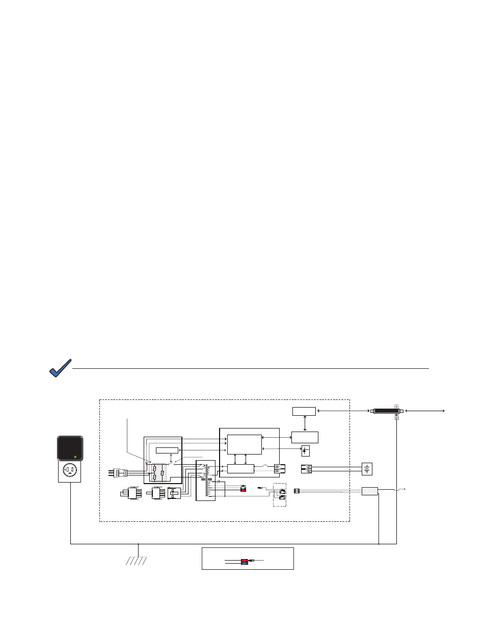
Fig. 1-3, Simplified Block Diagram
1.1.2 Standby Operation
When the incoming AC line voltage drops or rises significantly or a complete power
outage occurs, the control logic’s line monitor activates standby operation. During the
transfer from AC line to standby operation, the battery powered inverter comes online
as the isolation relay switches to prevent AC power from back-feeding to the utility.
The energy contained in the ferroresonant transformer continues to supply power to
the load. The following changes also occur within the power supply:
• The isolation relay opens to disconnect the AC line from the primary winding of
the ferroresonant transformer.
• The control logic drives the inverter FETs on and off at line frequency. This
switching action converts the DC battery current into AC current in the inverter
windings of the ferroresonant transformer, providing regulated power to the load.
• The control logic, which includes a microprocessor and other circuits to protect
the inverter FETs from overcurrent damage, monitors the condition of the
batteries and the inverter during standby operation. Since a prolonged AC line
outage would severely discharge the batteries, resulting in permanent damage,
the control logic disables the inverter when the batteries drop to approximately
10.5Vdc per battery (31.5Vdc in a three-battery set or 42.0Vdc in a four-battery
set).
When acceptable AC line voltage returns, the power supply returns to AC line
operation after a 20 to 40 second lag. This delay lets the AC line voltage and
frequency stabilize before the control logic phase-locks the inverter’s output to the
utility input. The control logic then de-energizes the isolation relay, reconnects the
AC line to the primary of the ferroresonant transformer and disables (turns off) the
inverter. This results in a smooth, in-phase transfer back to utility power without
interruption of service to the load. The battery charging circuit then activates to
recharge the batteries in preparation for the next power outage.
NOTE:
The output fuse has been removed from models of the XM2 Power Supply manufactured after July
2006.
Transformer
K1
RV1
RV3
RV2
63 Vac
75 Vac
C1
(+)
(-)
AC1
AC2
Power Distribution Board
Inverter Module Assembly
Inverter
Relay Control
AC Line Detector
and Control Logic
Circuits
Transponder
Optional
Communications
Card
Batteries
Black
Red
Red
Black
AC Output
Connectors
120Vac Jumper
240Vac Jumper
Input Select
Black
White
Red
Battery Circuit
Breaker
Control Bus
Output 1A
Output 1B
Isolation Relay
Optional Surge Protector -
Replaceable Primary Power Supply
Overvoltage protection
(plugged into upper receptacle
of parallel-wired outlet)
RemoteTemperature
Sensor
Littlefuse V320LA40BP Varistors
Secondary Power Supply Overvoltage protection
Coaxial surge protector (Gas Filled)
Transponder Overvoltage protection
(Alpha p/n 162-028-10)
Surge Protector
Earth Ground (Enclosure)
Black
White
Black
White
Coaxial Cable Power Inserter
(Alpha’s SPI)
Coaxial Network
87/89 Vac
Black
48 Vac
63 Vac
Black
Red
Blue
Transformer
AC Output
Output tap connector (shown in default 63Vac position)
Factory-set output tap connector
(settings for 48V/63V models shown below)
XM Series 2 Power Supply Chassis
Status Monitoring
Network
16
017-805-B0-010 Rev. K2