Intelligent cableups layout, Continued – Alpha Technologies XM2, XM2-HV, XM2-HP User Manual
Page 21
1.2
Intelligent CableUPS Layout
, continued
1.2.2
Inverter Module Overview, continued
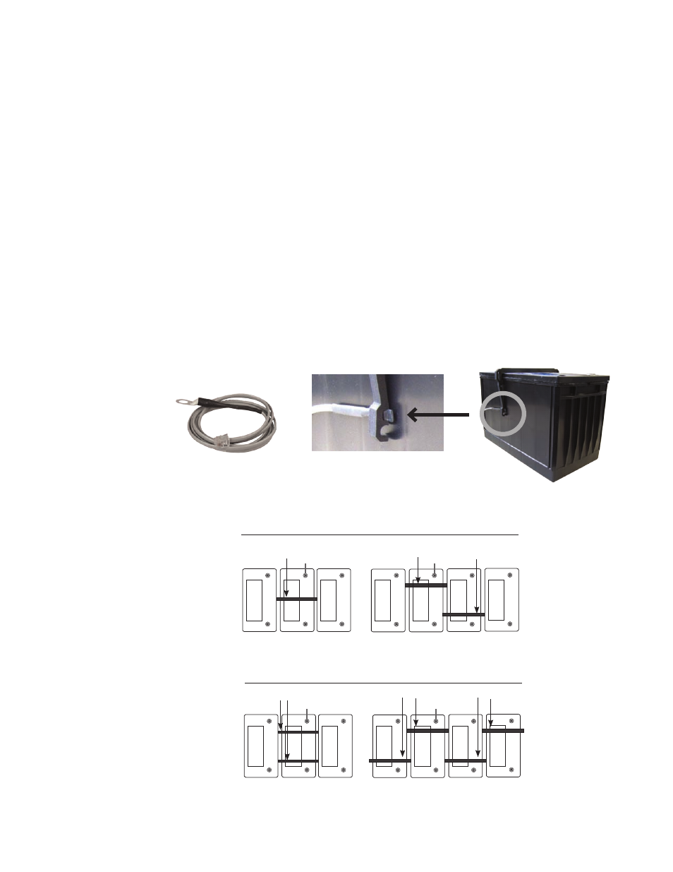
Fig. 1-8, Placement of Remote Temperature Sensor (RTS) on battery
Inverter Cooling Fan: The inverter module is equipped with a cooling fan that operates
during standby operation when the inverter heatsink temperature reaches 85°C. The fan
stays on until the temperature drops below 75°C. The fan also operates whenever a self-test
is in progress.
Temp Probe Connector:
The Remote Temperature Sensor (RTS) plugs directly into the
temperature probe (RJ-11C type) connector.
Batt Volt (Battery Test Point) [legacy models only]: With the battery breaker on and
battery string(s) connected, DC Output can easily be checked using the inverter module’s
battery test point. Use a DC voltmeter whenever checking the output.
The Remote Temperature Sensor is held in place on the AlphaCell 165, 195, 210 and 220
series batteries by a Battery Spacer Clip. To install, flex the clip and hook the retaining tabs
over the top of the battery and slide the sensor into place in the clip as shown below. For
domestic applications, use one battery clip per 36V battery string and two clips per 48V
battery string for optimal spacing. For International applications use two clips per 36V battery
string and four per 48V battery string. As an option to the Battery Spacer Clip, an RTS with
ring lug can be used (p/n 746-254-XX).
Fig. 1-9, Placement of Battery Spacer Clips on 36V and 48V battery strings
3
2
1
2
4
1
3
+
-
+
-
+
-
+
-
+
-
+
-
+
-
36V battery string
Battery Spacer Clips
(Domestic applications)
48V battery string
(Note: actual placement determined by battery arrangement)
3
2
1
2
4
1
3
+
-
+
-
+
-
+
-
+
-
+
-
+
-
Battery Spacer Clips
(International applications)
RTS Ring
Lug option
placement
RTS Ring
Lug option
placement
RTS Ring
Lug option
placement
RTS Ring
Lug option
placement
21
017-805-B0-010 Rev. K2