1 theory of operation, 1 ac (line) operation – Alpha Technologies XM2, XM2-HV, XM2-HP User Manual
Page 15
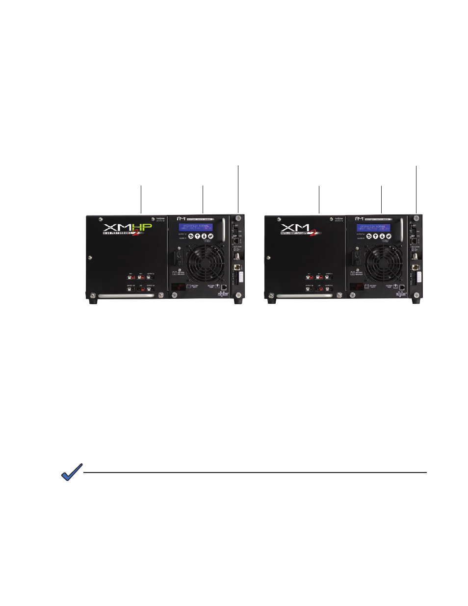
Fig. 1-1, XM2-HP Power Supply
1.1 Theory of Operation
The Intelligent CableUPS is comprised of the:
• Transformer module, which acts as a stand-alone line conditioner. The transformer
module contains a ferroresonant transformer, resonant capacitor, transfer isolation relay,
Power Distribution Board and the optional Protective Interface Module (PIM) board.
• Inverter module, which is required for standby operations and contains circuitry needed
for the three-stage temperature-compensated battery charger, DC to AC converter
(inverter), AC line detectors and Smart Display.
• Optional communications module, used to provide external status monitoring and
communications.
1.1.1 AC (Line) Operation
During AC Line operation, utility power is routed into the primary winding of the
ferroresonant transformer through the contacts of the transfer isolation relay.
Simultaneously, in the inverter, power is directed to the rectifier circuitry providing
power for the control circuitry. The bidirectional inverter also serves as a battery
charger during line operation. The ferroresonant transformer and an AC capacitor
form the resonant tank circuit, which provides excellent noise and spike attenuation,
output short circuit current limiting and output voltage regulation. The ferroresonant
transformer produces a
quasi square wave output which resembles a rounded
square wave.
When measuring the output voltage of ferroresonant transformers, use only a true RMS AC voltmeter.
Non-RMS reading meters are calibrated to respond to pure sine waves and do not provide an
accurate reading when measuring
quasi square wave output.
NOTE:
Fig. 1-2, Standard XM2 Power Supply
High Efficiency
Transformer Module
Intelligent Inverter
Module
DOCSIS
®
Communications
Module
Transformer Module
Intelligent Inverter
Module
DOCSIS
®
Communications
Module
15
017-805-B0-010 Rev. K2