2 communication and control connections, 3 quick start – Alpha Technologies AMPS80 HP User Manual
Page 61
59
Doc. #: 026-069-B0 Rev F
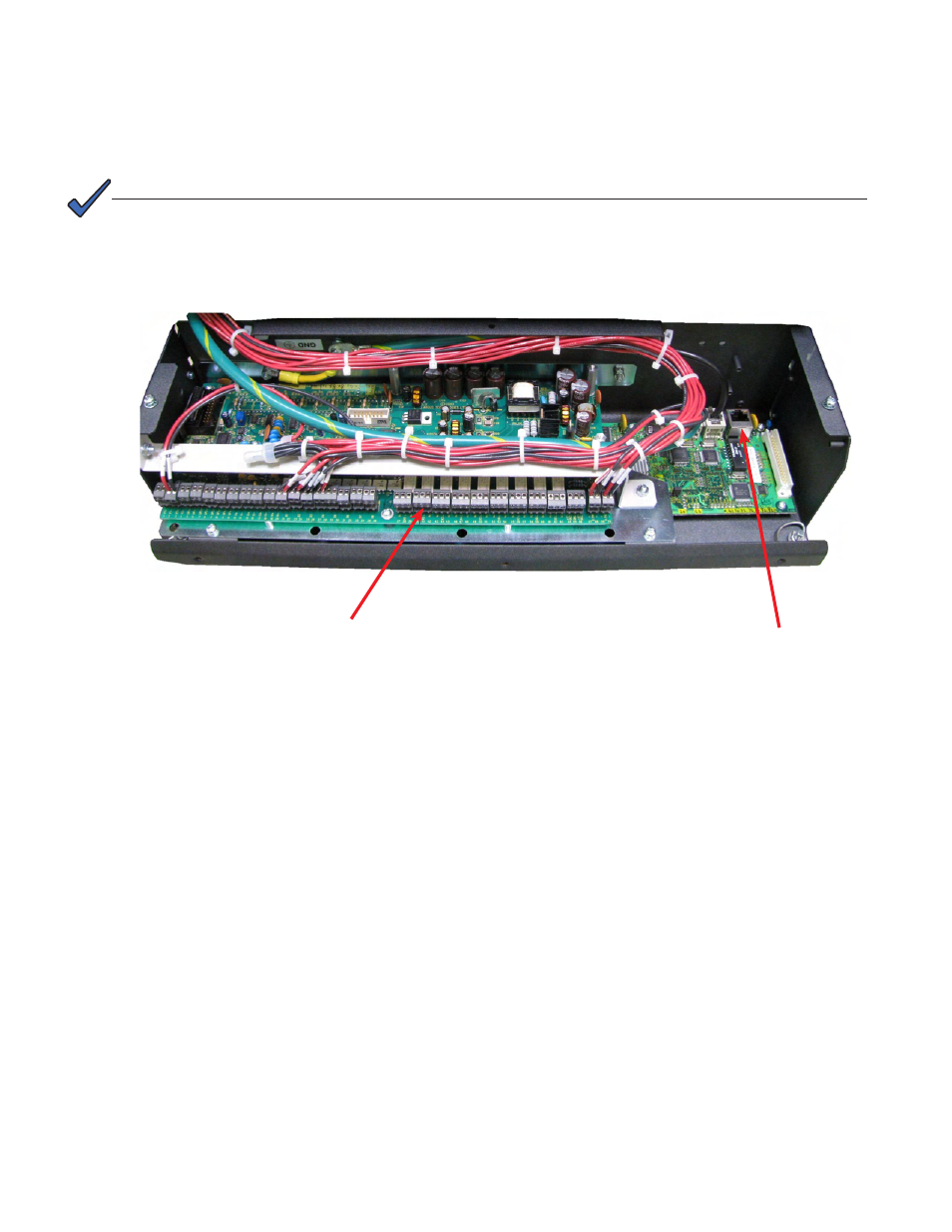
6.3.2 Communication and Control Connections
Remove two screws and fold the controller front panel down to access the communication and control con-
nectors.
6.3.3 Quick Start
1. To initiate a startup routine, switch on the power to the controller by closing the battery breaker. The
controller performs a short self-test as it boots up. Alarm alerts are normal. The LEDs perform a scrolling
pattern to indicate there is activity. Wait for the startup routine to finish.
2. Check and adjust alarms and control levels in the CXC submenus.
3. Check and adjust group settings in the INVERTERS and RECTIFIERS submenus; e.g. float, equalize
voltage, etc.
4. Verify COMMUNICATIONS settings as needed.
5. Program the CXC TEMP COMP and AUTO EQUALIZE settings as needed.
6. Test relay OUTPUT ALARM\CONTROLS as needed; e.g. Major Alarm, CEMF, etc.
Controller Ethernet port
Input and output signal connections
NOTE:
The breakers located at the top of the AMPS80 (see Figure 1) protect the wiring to the
CXC and alarm contacts of the different auxiliary contacts on the AC inverter input and out-
put breaker, the TVSS and the MBS.