Alpha Technologies AMPS80 HP User Manual
Page 52
Doc. #: 026-069-B0 Rev F
50
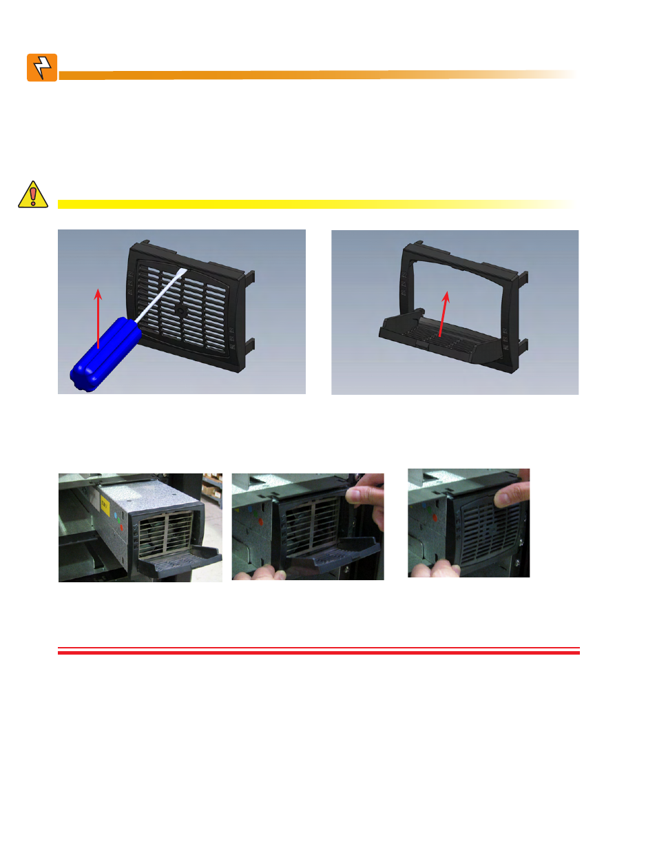
Insert a flat head screw driver into the center flap
notch and pry open the center flap. Then pull out the
module by pulling on the center flap with both hands.
Leave the module plastic front grill in the open/un-
locked position, then slide/push the module all the
way into the module slot, and then close the flap.
Unlock
Figure 30 —
Unlocking and locking an inverter module for removal or insertion
Figure 31 —
Inserting and removing an inverter module
1. Place module into shelf.
2. Press module into place and
ensure connection is engaged.
3. Close cover and snap module
into place. If cover does not close
easily, repeat Step 2.
Lock
WARNING!
Do not install all inverter modules at once but load one inverter module into an open slot for
each AC phase. This allow the initial set-up of the AC phases. All remaining modules will
automatically take on the configurations of these “seed” modules. See diagrams under Sec-
tion 8.1: Module Location Relative to System Wiring for AC phase locations. See below for
detailed module insertion/removal instructions. You may not want to close/lock the grill at
this time because the module may have to be removed at a later stage.
CAUTION!
Improper installation or removal of modules can break latching components.