3 dc connections, 1 dc battery cabling – Alpha Technologies AMPS80 HP User Manual
Page 45
43
Doc. #: 026-069-B0 Rev F
5.3 DC Connections
• Access to connection points is provided from the front of the system rack.
• DC wires enter the cabinet either through the top or the bottom of the cabinet.
• A low voltage disconnect should be provided with the battery system.
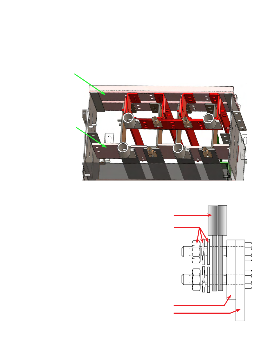
Figure 22 —
DC connections - top view
DC+ bus
: DC1, DC2, DC3, DC4 input con-
nectors shown with one 4DC tie bar
DC- bus
: DC1,
DC2, DC3, DC4
5.3.1 DC Battery Cabling
DC battery cable terminations are de-
signed for two-hole spade lugs crimped to
the cabling, then attached to the bus bars.
Depending upon the gauge of the input
wiring used, the connections may be made
either singly or with two back-to-back lugs
per mounting hole.
Each bar (DC+, DC-) can accept seven
2-hole ½" mounting lugs on 1-3/4" centers
or seven 2-hole 3/8" lugs on 1" centers.
Torque specifications for DC wiring (3/8"
bolts that attach the DC lugs at the back
of the DC distribution box) are 190 – 240
inch/lbs (21.5 – 27.1 N-m).
Input cabling
3/8" or 1/2" hardware
Tie bar
Bus bar
Figure 23 —
Cabling and hardware arrangement