Alpha Technologies AMPS80 HP User Manual
Page 40
Doc. #: 026-069-B0 Rev F
38
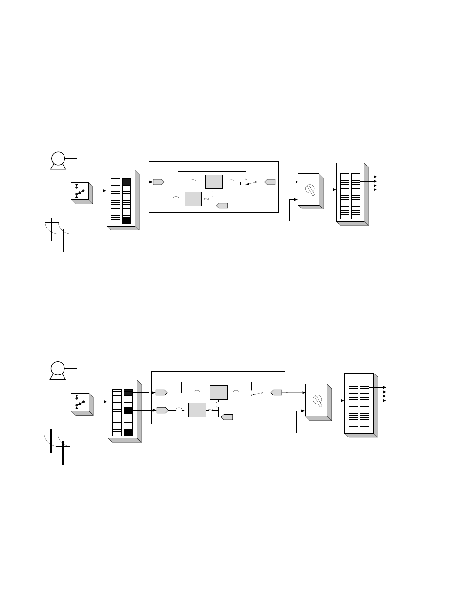
Figure 17 —
Representative system wiring for AMPS inverter or hybrid system with MBS with single AC input feed.
4.6.2 AMPS80 HP with External Maintenance Bypass Switch
These diagrams show the logical internal connections. They are not a detailed representation of the actual
internal system wiring.
Figure 18 —
Representative system wiring for AMPS inverter system with independent AC input feed for MBS
Generator
MAIN
Distribution
Panel
Utility
Dedicated
UPS
Distribution
Panel
Critical
Systems
Power
External
Maintenance
Bypass
Switch
UPS
BYPASS
Automatic
Transfer
Switch Break
Before Make
Rectifier
(optional)
Inverters
Make before break
manual bypass
switch (optional)
AMPS 80 HP
AC Input
AC Output
Battery
Connection
DC breakers
(optional)
AMPS80 HP Installation Diagram for
single AC input feed for the
Inverter/MBS and Rectifiers
Generator
MAIN
Distribution
Panel
Utility
Dedicated
UPS
Distribution
Panel
Critical
Systems
Power
External
Maintenance
Bypass
Switch
UPS
BYPASS
Automatic
Transfer
Switch
Rectifier
(optional)
Inverters
Make before break
manual bypass
switch (optional)
AMPS 80 HP
Inverter AC Input
AC Output
Battery
Connection
DC breakers
(optional)
400A for AMPS80-3-75
AMPS80-2-40
200A for AMPS80-3-30
AMPS80-2-20
AMPS80 HP Installation Diagram for
separate AC input feeds for the
Inverter/MBS and Rectifiers
Rectifier AC Input