Franklin Fueling Systems TS-LS300 AutoLearn Pressure-Based Electronic Line Leak Detector System Users Guide User Manual
Page 23
ELECTRICAL INSTALLATION & WIRING
Page
3-5
3
LS300 User’s Guide
4.)
Remove a portion of the cable jacket (service-loop) inside the J-Box, and install the no-strip electrical
connectors inside the J-Box (see Figures 3-2 & 3-3).
5.)
Verify that all connections are correct and that the like colored and unstripped wires are fully inserted
into the no-splice connectors (RED to RED, WHITE to WHITE, BLACK TO BLACK, and SHIELD
DRAIN to SHIELD DRAIN) and are spliced together... make sure that the black, oval-shaped
compression part is firmly seated down into the connector with slipjoint pliers (see Figures 3-2 & 3-
3). Install J-Box cover after wire-splicing is completed and checked.
6.)
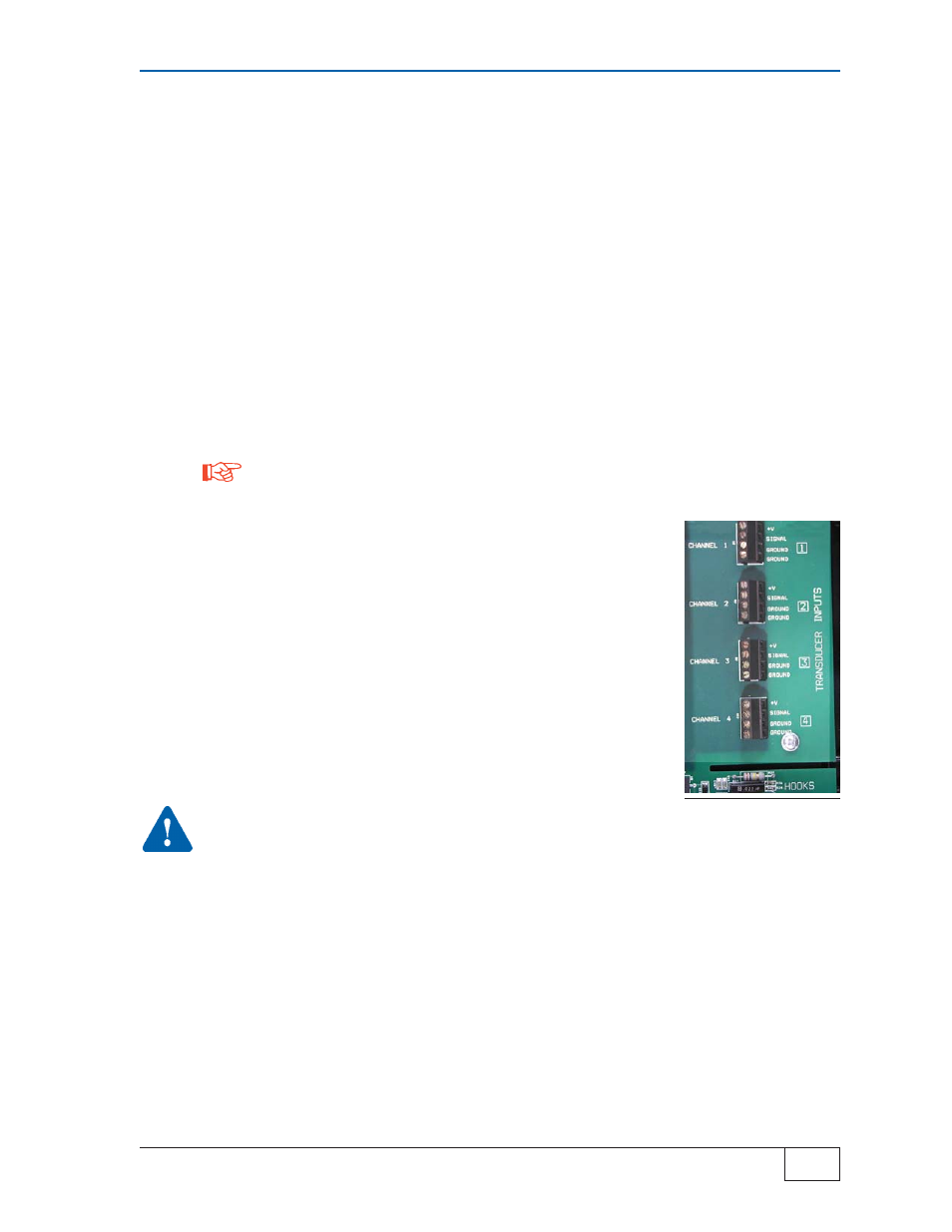
Remove the metal Terminal Safety Guard and Wire LSU300 Transducers to the Transducer Input
channel terminals inside the LS300 console. See Figure 3-4 for Tank, Line, and Product
associations, and TABLE 3-1 for wiring. Maintain these associations accurately when wiring
Transducer and Hook Input terminals.
Channel N must operate the STPs at Tank/Line N
A.)
Strip off 3/16 of a inch (5 mm) of insulation from the ends of each conductor
B.)
Wire Transducers # 1 – 4 (see Figure 3-4). Make sure all wires
are fully inserted and clamped at the terminal block. Make sure
no stray strands of wire are shorting to adjacent terminal block
connections.
C.)
Install the metal Terminal Safety Guard after verifying all
Transducer Input Channel wiring is correct
D.)
Verify that all splices in the manhole Junction Boxes are
accurate
E.)
Lastly, install the Explosion proof/Weatherproof Junction Box
Covers
WARNING
Never power up the LS300 console when the terminal
safety guard is removed
Basic Installation & Wiring – all Applications (Continued... )
NOTE
Photo 3-3
Transducer Inputs