Defining the audio/rs-232 wire pair, Defining the audio/rs-232 wire pair -38, Input – Extron Electronics MTPX Series User Guide User Manual
Page 64: Configuration, And input, Preliminar y, Operation, cont’d
Operation, cont’d
MTPX Twisted Pair Matrix Switchers • Operation
3-38
PRELIMINAR
Y
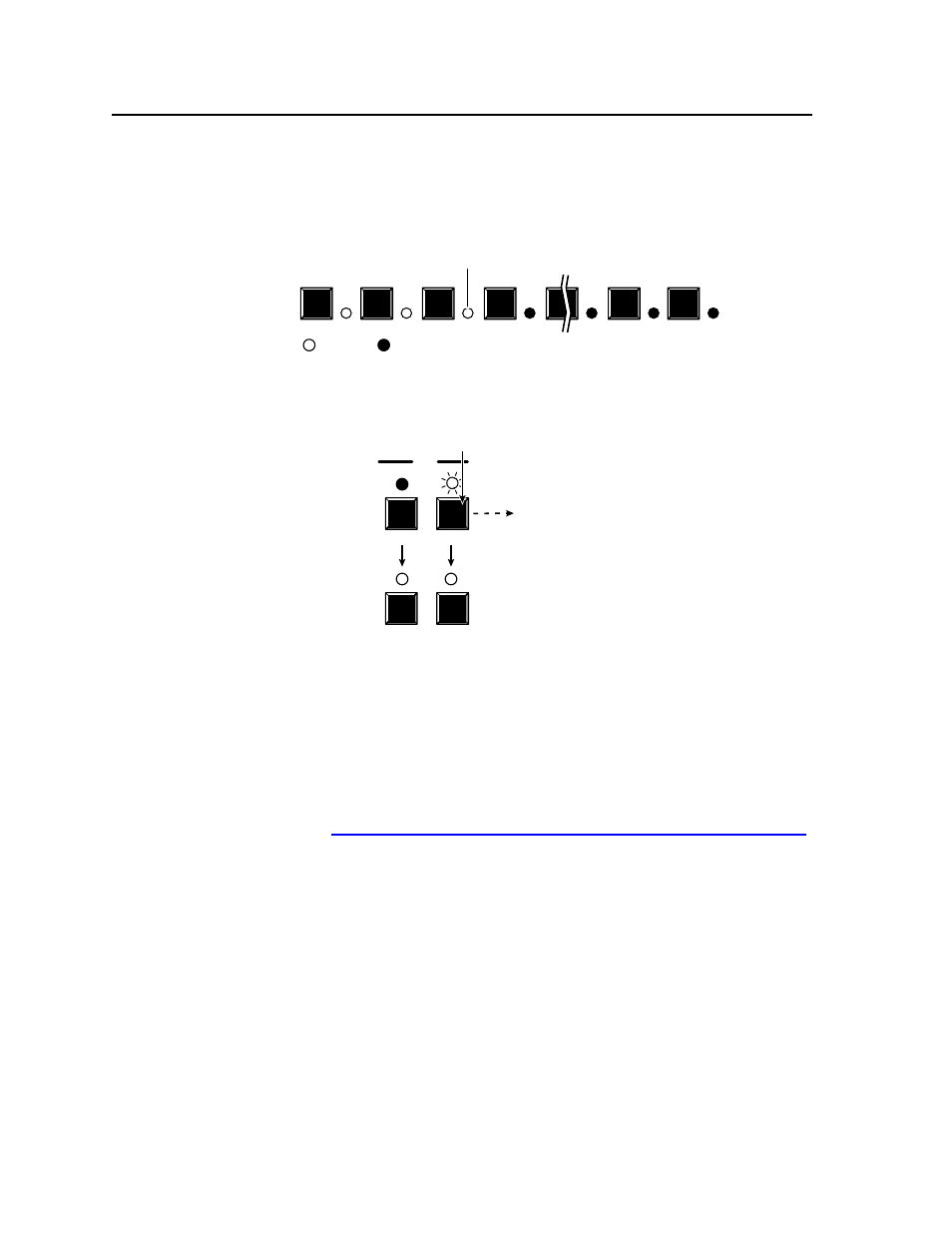
Figure 3-55 shows the same volume (61%) as in figure 3-54, but displayed on a
32-input-button switcher, such as an MTPX Plus 3216.
17
18
19
20
30
31
32
The input LEDs display the selected output's audio volume level.
In this example, the lit input buttons indicate 61 percent of the applied audio input.
The unlit input buttons indicate an audio volume attenuation of 26 dB.
–26 dB attenuation, 61% volume
= Lit LED,
= unlit LED
Figure 3-55 — Volume display on a 32-input-button switcher
5
.
Press and release the Audio button (figure 3-56).
VIDEO AUDIO
I/O
VIDEO AUDIO
The Audio LED stops blinking and lights steadily.
The Video button lights.
Press the Audio button to exit audio mode.
All input LEDs and output LEDs
return to the unlit state.
Figure 3-56 — Deselect Audio mode
Defining the Audio/RS-232 wire pair
N
The audio/RS-232 TP input settings (RS-232 or audio) are protected when front
panel
Lock mode 2 is selected. You can view the settings in Lock mode 2 but
you cannot change them from the front panel. See “Setting the front panel locks
(
Executive modes)” on page 3-40.
The switcher is compatible with MTPs that transmit and receive mono audio and
those that transmit and receive RS-232 serial data. You must configure the switcher
for the appropriate audio/RS-232 input for each TP input. Each TP input’s audio/
RS-232 settings can be viewed and changed from the front panel.