Preliminar y, Installation, cont’d, Rj-45 connector – Extron Electronics Matrix 12800 Series User Guide User Manual
Page 31
Installation, cont’d
Matrix 12800 Switchers • Installation
2-16
PRELIMINAR
Y
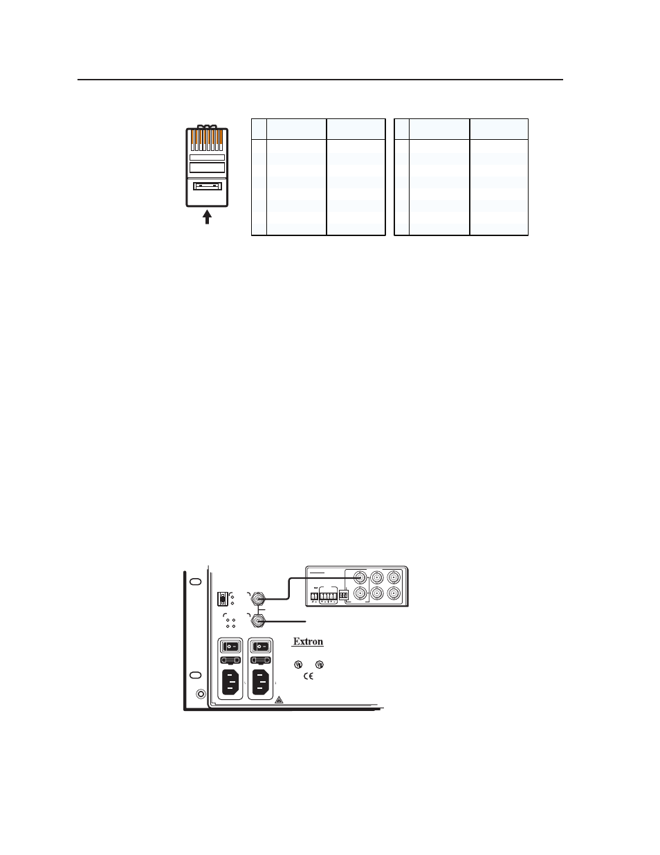
A cable that is wired as T568A at one end
and T568B at the other (Tx and Rx pairs
reversed) is a "crossover" cable.
A cable that is wired the same at both ends is
called a "straight-through" cable, because
no pin/pair assignments are swapped.
12345678
RJ-45
Connector
Insert Twisted
Pair Wires
Pins:
Crossover Cable
Straight-through Cable
Pin
1
2
3
4
5
6
7
8
Wire color
White-green
Green
White-orange
Blue
White-blue
Orange
White-brown
Brown
Wire color
T568A
T568B
End 1
End 2
End 1
End 2
White-orange
Orange
White-green
Blue
White-blue
Green
White-brown
Brown
Pin
1
2
3
4
5
6
7
8
Wire color
White-orange
White-green
Blue
White-blue
White-brown
Brown
Wire color
T568B
T568B
White-orange
Orange
Orange
White-green
Blue
White-blue
Green
Green
White-brown
Brown
Figure 2-15 — RJ-45 connector and pinout tables
External sync connections (wideband and video BMEs only)
For NTSC, PAL, or SECAM video, when the switcher switches between inputs, the
resulting change in image should be seamless, or clean. The Matrix 12800 switcher
can use an external signal to synchronize switching during the vertical interval.
Without the external sync locking feature, switching between inputs can result in a
brief rolling (sync loss) or a brief change in the picture size.
N
External sync only works for inputs that have been virtualized as NTSC, PAL,
or SECAM video only, not for inputs virtualized as RGB video.
p
External Sync In connector — Connect an external sync signal to this BNC
connection for genlocking the video signal in broadcast or other sync-critical
applications.
External Sync Out connector —
Connect any downstream equipment that
requires genlocking to this BNC connector to route the external sync signal
throughout the system in broadcast or other sync-critical applications.
Figure 2-16 shows a basic external sync configuration. The Ext Sync In connector
receives a timing signal. The Out connector allows the signal to be passed on to
another video device, if required.
POWER
12V
.2A MAX
L
R
4
3
2
1
6
5
PA
L
NTSC
BLA
CKBURST
BLACKBURST
COLORBARS
-10
+4
1 2 3
ON
1 KHZ
AUDIO
BBG 6 A
BLACKBURST AND AUDIO
GENERATOR
DISCONNECT BO
TH PO
W
ER CORDS BEFORE SER
VICING.
100-240V 5.0A MAX 50/60Hz FUSE 250V 5.0A
T
100-240V 5.0A MAX 50/60Hz FUSE 250V 5.0A
T
PRIMARY AC
POWER INPUT
POWER SUPPLIES
CPU STATUS
LISTED
1T23
I.T.E.
BME
PRIMARY
REDUNDANT
CAUTION
For protection against risk of
fire, replace only with same
type and rating of fuse.
PRIMARY
REDUNDANT
REDUNDANT AC
POWER INPUT
ANAHEIM, CA
SYNC
To Next Device
BBG 6A
MADE IN USA
+V -V
ADDRESS
4
-
+
IN
OUT
Figure 2-16 — Simple external sync connection example