Ground, Ul guidelines for ground, Power – Extron Electronics Matrix 12800 Series User Guide User Manual
Page 23: Ground -8, Ul guidelines for ground -8, Power -8, Preliminar y, Installation, cont’d, Figure 2-6 — connecting power, Primary ac power input redundant ac power input
Installation, cont’d
Matrix 12800 Switchers • Installation
2-8
PRELIMINAR
Y
Ground
d
Ground terminal — If the power outlets do not provide connections to
the protective ground of the building
, connect ground straps between this
terminal lug on all BMEs and a hard building ground. Secure the ground
straps with the nut and washer included with each BME.
N
You are responsible for providing the ground straps.
N
Some earlier BMEs do not have the ground terminal.
UL guidelines for ground
N
The equipment is intended to be used in a location having equipotential bonding.
1
.
The building installation shall provide a means for connection to protective
earth; and
2
.
The equipment is to be connected to that means; and
3
.
A SERVICE PERSON shall check whether or not the socket-outlet from
which the equipment is to be powered provides a connection to the building
protective earth (ground). If not, the SERVICE PERSON shall arrange for the
installation of a PROTECTIVE EARTHING CONDUCTOR from the separate
protective earthing terminal to the protective earth wire in the building.
Power
e
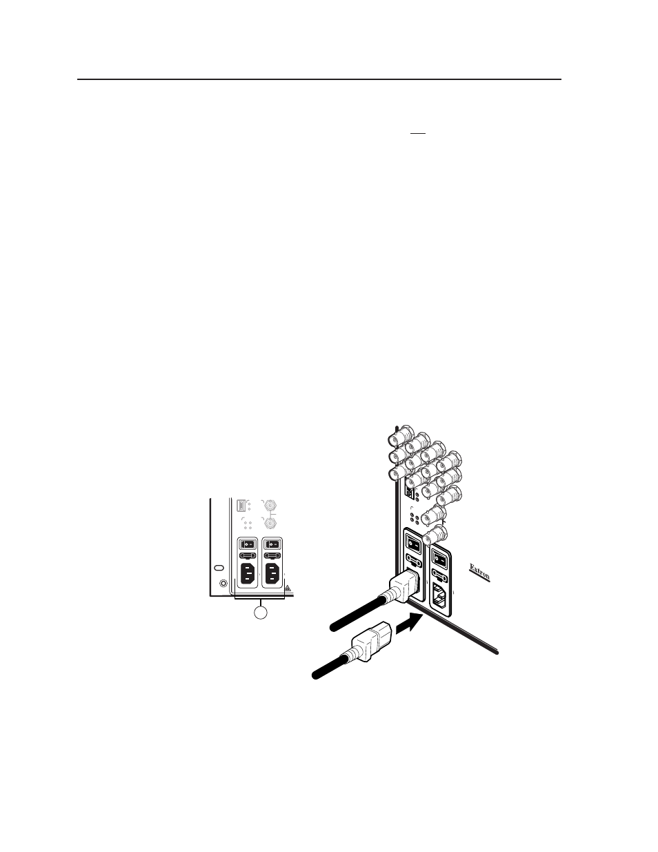
Primary and Redundant AC Power Input connectors — Connect a standard
IEC power cord between the rear panel Primary AC Power Input connector
and a 100 to 240VAC, 50 Hz or 60 Hz power source (figure 2-6).
POWER SUPPLIES
CPU STATUS
BME
PRIMARY
REDUNDANT
PRIMARY
REDUNDANT
SYNC
+V -V
ADDRESS
4
-
+
IN
OUT
DISCONNECT BO
TH PO
WER CORDS BEFORE SER
VICING.
100-240V 5.0A MAX 50/60Hz FUSE 250V 5.0A
T
100-240V 5.0A MAX 50/60Hz FUSE 250V 5.0A
T
PRIMARY AC
POWER INPUT
REDUNDANT AC
POWER INPUT
5
BME
ADDRES
S
ANAHEIM,
CA
MADE IN USA
4
For prote
ction a
gainst
risk of
fire
, replac
e only wi
th sam
e
type an
d ratin
g of fuse
.
CA
UTIO
N
REDUN
DANT
AC
PO
WER INPUT
100-240V 0.5A MAX 50/60Hz
PRIMAR
Y AC
PO
WER INPUT
100-240V 0.5A MAX 50/60Hz
PRIMAR
Y
REDUND
ANT
PO
WER SUPPLIES
+v -v
CPU S
TATUS
PRIMAR
Y
REDUND
ANT
SYN
C
OU
T
IN
Primary AC
Power Input
Redundant AC
Power Input
Figure 2-6 — Connecting power
If this BME is equipped with redundant power supplies A and B, connect a
second IEC power cord between the Redundant AC Power Input connector
and either an uninterruptible power source or a power source that is
completely independent from the primary power source.