Preliminar y, Installation, cont’d, Fpc comm port — (future capability) – Extron Electronics Matrix 12800 Series User Guide User Manual
Page 29: Figure 2-13 — connecting a control keypad
Installation, cont’d
Matrix 12800 Switchers • Installation
2-14
PRELIMINAR
Y
l
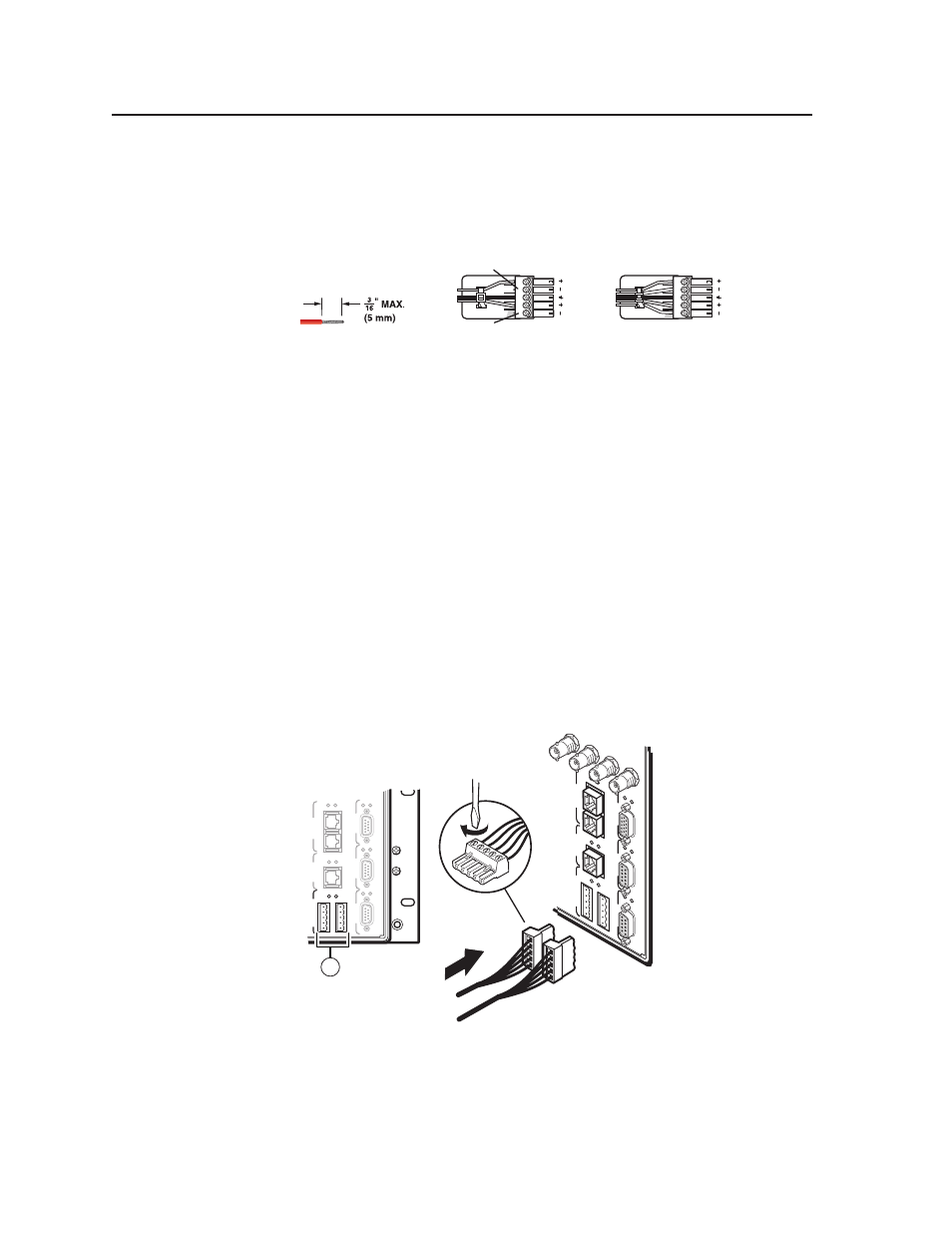
Audio outputs connectors — These 3.5 mm, 5-pole captive screw connectors
output the selected unamplified, line level audio. Connect audio devices,
such as an audio amplifier or powered speakers.
See figure 2-12 to properly wire an output connector. Use the supplied tie-
wrap to strap the audio cable to the extended tail of the connector.
Unbalanced Stereo Output
Balanced Stereo Output
Do not tin the wires!
Tip
No Ground Here
No Ground Here
Tip
LR
Sleeves
Tip
Ring
Tip
Ring
LR
Sleeves
Figure 2-12 — Captive screw connector wiring for audio output
C
For unbalanced audio, connect the sleeves to the ground contact.
DO NOT connect the sleeves to the negative (-) contacts.
N
By default, the audio gain of each output is set to 0 dB (unbalanced) and 6 dB
(balanced). To reduce this setting by 6 dB (-6 dB [unbalanced], 0 dB [balanced]),
see “
Setting the default audio gain
” in chapter 6, “Upgrades and Maintenance“.
By default, the audio output follows the video switch. Audio breakaway,
is available via the front panel, either RS-232/RS-422 port, or the Ethernet
port. See the Matrix 12800 Switcher Front Panel Controller User Guide, and
Virtualization/Control Software
Remote control panel, front panel controller, and Ethernet connections
m
FPC Comm port — (FUTURE CAPABILITY)
n
MCP/MKP Comm ports — For systems consisting of a single switcher
or for BME 0 on a multi-BME system, if desired, connect an MKP 1200
remote keypad to either of these 3.5 mm, 5-pole captive screw connectors
(figure 2-13). See the MKP 1200 User Guide, for details.
ETHERNET
BME COMM
IN
OUT
FPC COMM
Tx
Rx
Tx
Rx
Tx
Rx
Tx
Rx
Tx
Rx
SECOND
AR
Y
PRIMAR
Y
RS 232/422
RS 232/422
MCP/MKP COMM
A B C D
E
Tx
Rx
14
SECOND
AR
Y
MCP/MKP COMM
ETHERNET
BME COMM
IN
OUT
A B C D
E
PRIMAR
Y
FPC COMM
Tx
Rx
Tx
Rx
Tx
Rx
Tx
Rx
Tx
Rx
Tx
Rx
RS 232/422
RS 232/422
80
96
112
128
Figure 2-13 — Connecting a control keypad