Preliminar y, Installation, cont’d, Figure 2-3 — daisy-chaining bmes – Extron Electronics Matrix 12800 Series User Guide User Manual
Page 21
Installation, cont’d
Matrix 12800 Switchers • Installation
2-6
PRELIMINAR
Y
b
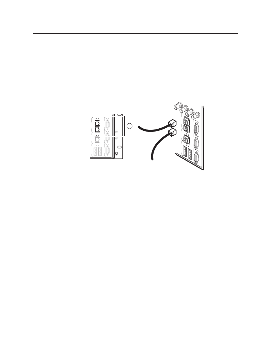
BME COMM interconnect ports — If the Matrix 12800 system consists of
more than one BME, the BMEs must be connected together in a daisy chain
using Extron-supplied RJ-45 cables.
Connect the first daisy chain from the BME Comm Out connector on BME 0 to
the nearest BME Comm In connector on the BME (figure 2-3). In a rack whose
BMEs are numbered sequentially, this would be BME 1. But, since not all
systems are configured alike, call this module BME n.
Connect the next RJ-45 cable from the BME Comm Out connector on BME n to
the BME Comm In connector on nearest unconnected BME (BME n+1) .
SECOND
AR
Y
MCP/MKP COM
M
ETHERNET
BME COM
M
IN
OUT
A B C D
E
PRIMAR
Y
FPC COM
M
Tx
Rx
Tx
Rx
Tx
Rx
Tx
Rx
Tx
Rx
Tx
Rx
RS 232/422
RS 232/422
Rx
2
SECOND
AR
Y
MCP/MKP COMM
ETHERNET
BME COMM
IN
OU
T
A B C D
E
PRIMAR
Y
FPC COMM
Tx
Rx
Tx
Rx
Tx
Rx
Tx
Rx
Tx
Rx
Tx
Rx
RS 232/422
RS 232/422
80
96
112
128
From BME 0
To BME 2
BME 1
Figure 2-3 — Daisy-chaining BMEs
Continue connecting RJ-45 cables from the BME Comm Out connector on
each daisy-chained module to the BME Comm In connector on the next
module until all modules are included in the chain. When all of the BMEs are
connected, each of the BMEs in the system is connected to at least one other
BME via the BME Comm connectors.