5 connecting the lines – YSI P 700 IQ Analyzer User Manual
Page 38
38
ba76133e01
09/2013
P 700 IQ
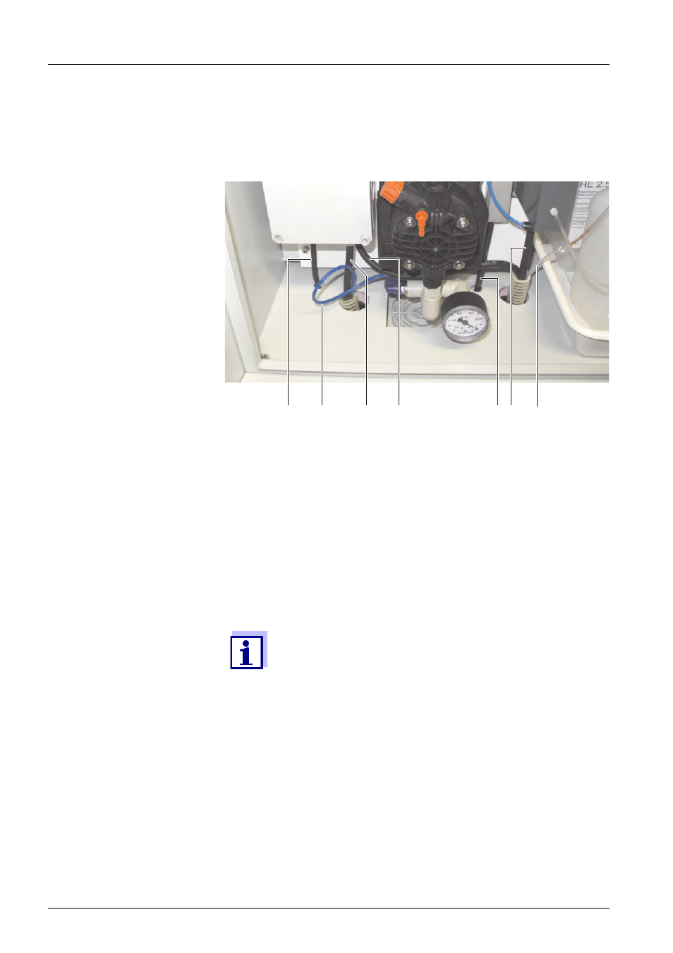
3.3.5 Connecting the lines
Fig. 3-16, 38 shows the housing with the completely connected lines
including the accessories and all options:
Fig. 3-16: Completely connected lines
Proceed as follows to connect the individual lines:
1
Connect the intake tube (2) to the filtration pump.
2
Insert the outlet of the overflow vessel and the outlet of the pho-
tometer unit into the sleeve tube of the return tube.
3
Connect the IQ S
ENSOR
N
ET
cable to the MIQ/WCA 232. See
section 3.3.5.1 Connecting the IQ S
4
Connect the power line (1) and, if necessary, the heat tracing
lines (3 and 4) to the power supply box. See section 3.3.5.2 Con-
necting the power line and heat tracing lines, 40.
5
Tighten all cable glands after the connections have been made.
1
2
3
4
6
5
7
1 Power line
2 Intake tube
3 Heat tracing of the suction line (option)
4 Heat tracing of the return tube (option)
5 IQ S
ENSOR
N
ET
cable
6 Outlet of the overflow vessel
7 Outlet of the photometer unit
The liquid from the return tube must be able to drain off
freely (downward slope).