Typical bypass operation, Overload protection – Bell & Gossett 176R0649C Technologic 502 Series Pump Controller User Manual
Page 7
7
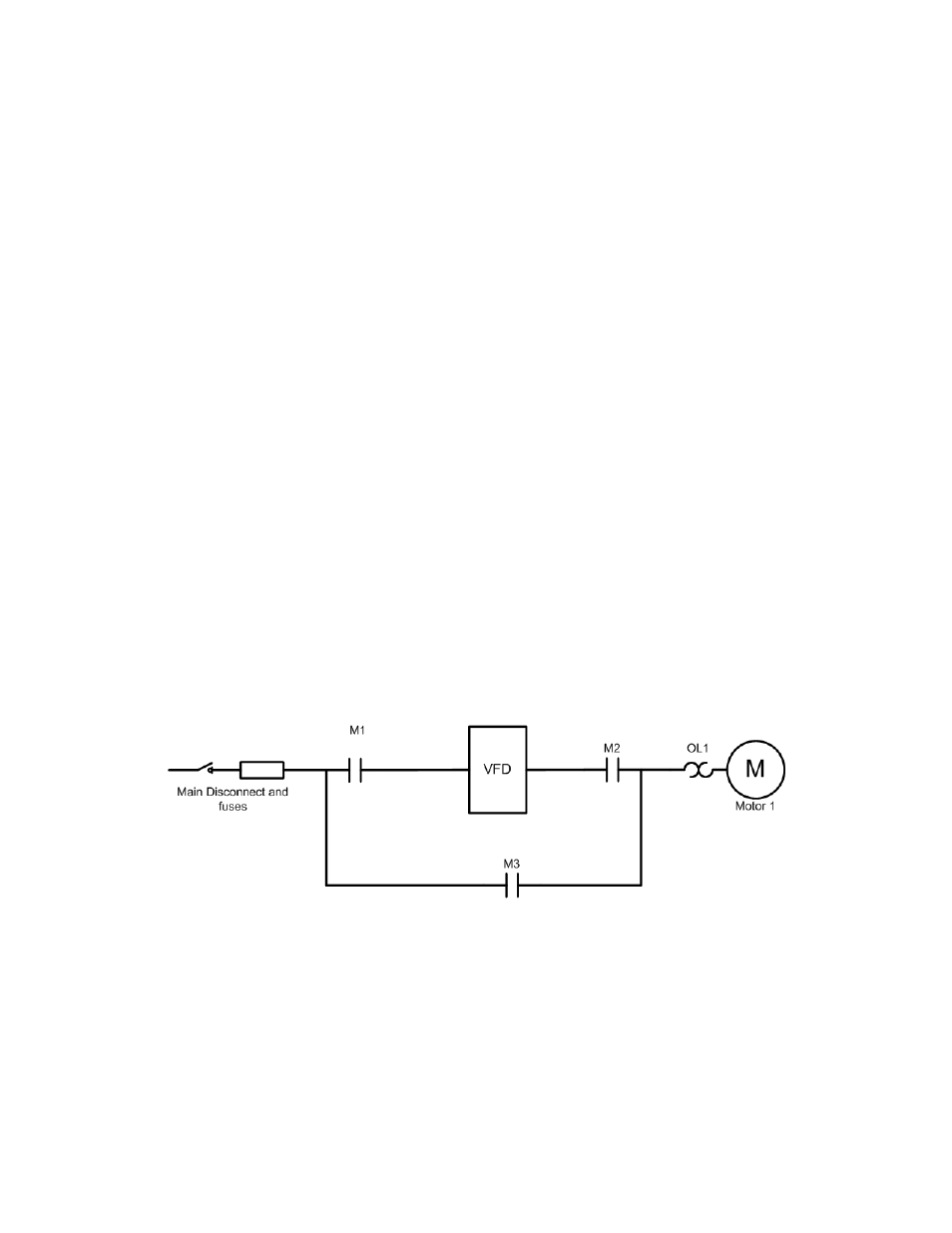
Figure 1-3. Basic 3-contactor Bypass Functions
Typical Bypass Operation
With contactors M1 and M2 closed and contactor M3
open (see Figure 1-3), the pump is controlled by the
drive. Opening contactor M2 removes power to the
pump but allows the controller to remain powered.
This is the test mode and only available in the three-
contactor configuration shown. With contactors M1
and M2 open and contactor M3 closed, the pump
runs in bypass from the line input. For a two-contactor
configuration, M1 is absent. In this case, contactors
M2 and M3 control the options for running in drive or
bypass mode. The figure illustrates a drive disconnect
and fuses.
Overload Protection.
This thermally activated device provides mechanical
overload protection for the pump(s) while in bypass
operation. It measures motor current and is factory set
to the full load amps (FLA) of the pump. A 1.2 x FLA
service factor is built-in and maintained. Should the
motor current increase above that value, the overload
will calculate the level of increase to activate timing
for the trip function. The higher the current draw, the
quicker the trip response. The overload provides
Class 20 motor protection.