Warning, Control wiring, Drive control terminals – Bell & Gossett 176R0649C Technologic 502 Series Pump Controller User Manual
Page 18
18
Control Wiring
• It is recommended that control wiring is
rated for 600 volts for 480 V and 600 V
drives and 300 volts for 200-240 V drives.
• Isolate control wiring from high power
components in the drive.
WARNING
!
r
un
input
powEr
,
motor
wiring
and
control
wiring
in
tHrEE
sEparatE
mEtallic
conduits
or
racEways
for
HigH
frEquEncy
noisE
isolation
. f
ailurE
to
isolatE
powEr
,
motor
and
control
wiring
could
rEsult
in
lEss
tHan
optimum
drivE
and
associatEd
EquipmEnt
pErformancE
.
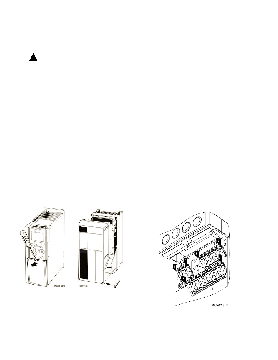
Figure 3-8. Control Terminals Access
Definitions of the drive terminals are summarized in
Table 3-3. Figure 3-9 shows the removable controller
connectors and terminals.
•
Connector 1 provides four programmable
digital inputs, two additional digital terminals
programmable as input or output, a 24 VDC
terminal supply voltage, and a common for
optional customer supplied 24 VDC voltage.
•
Connector 2 is for the serial
communications EIA-485 connector with
terminal 68 (+) and 69 (-).
•
Connector 3 provides two analog inputs,
one analog output, 10 VDC supply voltage,
and commons for the inputs and output.
•
Connector 4 is a USB port available for
use with the MCT-10 drive programming
software.
• Also provided are two Form C relay outputs
that are in various locations depending upon
the controller configuration and size.
Drive Control Terminals
Figure 3-9. Drive Control Terminals
Control Wiring Access
• For units 5 hp or less (208 V) and 10 hp or
less (480 V), remove access cover plate with
screw driver. (See Figure 3-8.)
• For larger size units, remove front cover of
unit to access internally mounted control
terminals. (See Figure 3-8.)