Mcb-101 master control board, Mcb101 master board drive terminals, Table 3-3. drive control terminals functions – Bell & Gossett 176R0649C Technologic 502 Series Pump Controller User Manual
Page 19
19
Table 3-3. Drive Control Terminals Functions
Terminal No.
Function
01, 02, 03
04, 05, 06
Form-C relay output. Useable for AC or DC voltage and
resistive or inductive loads. See drive support materials for
details on voltage and current ratings and relay location.
12, 13
24 VDC digital supply voltage. Useable for digital inputs and
external transducers. To use the 24 VDC for digital input
common, program parameter 5-00 for PNP operation.
Maximum output current is 200 mA total for all 24V loads.
18, 19, 32, 33
Digital inputs. Selectable for NPN or PNP function in
parameter 5-00. Default is PNP.
27, 29
Digital inputs or outputs. Programmable for either. Parameter
5-01 for terminal 27 and 5-02 for 29 selects input/output
function. Default setting is input.
20
Common for digital inputs. To use for digital input common,
program parameter 5-00 for NPN operation.
39
Common for analog output.
42
Analog output. Programmable for various functions in
parameter 6-5x. The analog signal is 0 to 20 mA or 4 to 20 mA
at a maximum of 500 Ω.
50
10 VDC analog supply voltage. 15 mA maximum commonly
used for a potentiometer or thermistor.
53, 54
Analog input. Selectable for voltage (0-10 V) or current (0- or
4-20 mA). Closed is for current and open is for voltage.
Switches are located on the drive control card behind the
removable LCP. See drive support materials for details.
55
Common for analog inputs.
61
Common for serial communication. Do not use to terminate
shields. See drive support materials for proper shield
termination.
68 (+), 69 (-)
RS-485 interface. When the drive is connected to an RS-485
serial communication bus, a drive control card switch is
provided for termination resistance. ON for termination and
OFF for no termination. See drive support materials for details.
MCB101
master board
Drive terminals
R1
249W
3
4
7
6
5
9
10
1
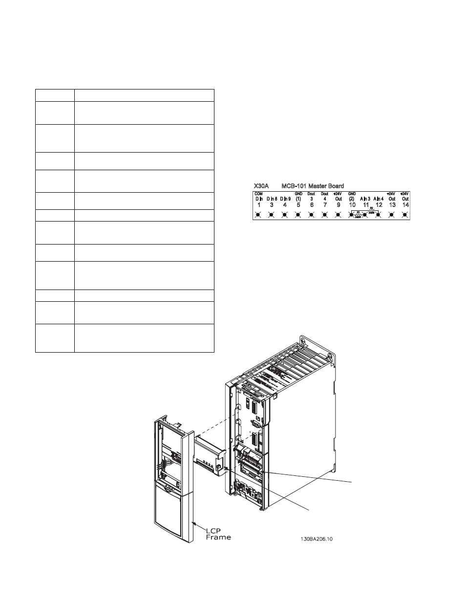
MCB-101 Master Board
11 12
X30A
13 14
D in
COM
D in 8 D in 9 (1)
GND
3
Dout
4
Dout
Out
+24V
(2)
GND
A in 3 A in 4 Out
+24V
Out
+24V
R2
249W
MCB-101 Master Control Board
Figure 3-10. Master Board Control Terminals
Figure 3-11. Master Board Terminals Location
The Master drive only contains the MCD-101 Master
Board which features additional programmable
connection terminals (see Figure 3-10). Typically,
differential pressure switches, remote system run and
system status, and an optional low suction pressure
switch are connected to these terminals. (See Figure
3-12, Control Wiring Schematic Diagram.)
notE
s
EE
f
igurEs
3-12
and
3-13
for
powEr
,
motor
and
control
wiring
diagrams
.
notE
s
EE
f
igurEs
3-12
and
3-13
for
powEr
,
motor
and
control
wiring
diagrams
.