Warning, Electrical installation, Figure 3-4. power connections – Bell & Gossett 176R0649C Technologic 502 Series Pump Controller User Manual
Page 14
14
WARNING
!
i
nducEd
v
oltagE
!
r
un
output
motor
cablEs
from
multiplE
drivEs
sEparatEly
.
i
nducEd
voltagE
from
output
motor
cablEs
run
togEtHEr
can
cHargE
EquipmEnt
capacitors
EvEn
witH
tHE
EquipmEnt
turnEd
off
and
lockEd
out
. f
ailurE
to
run
output
cablEs
sEparatEly
could
rEsult
in
dEatH
or
sErious
injury
.
notE
r
un
drivE
input
powEr
,
motor
wiring
,
and
control
wiring
in
tHrEE
sEparatE
mEtallic
conduits
or
racEways
for
HigH
frEquEncy
noisE
isolation
. f
ailurE
to
isolatE
powEr
,
motor
,
and
control
wiring
could
rEsult
in
lEss
tHan
optimum
controllEr
and
associatEd
EquipmEnt
pErformancE
.
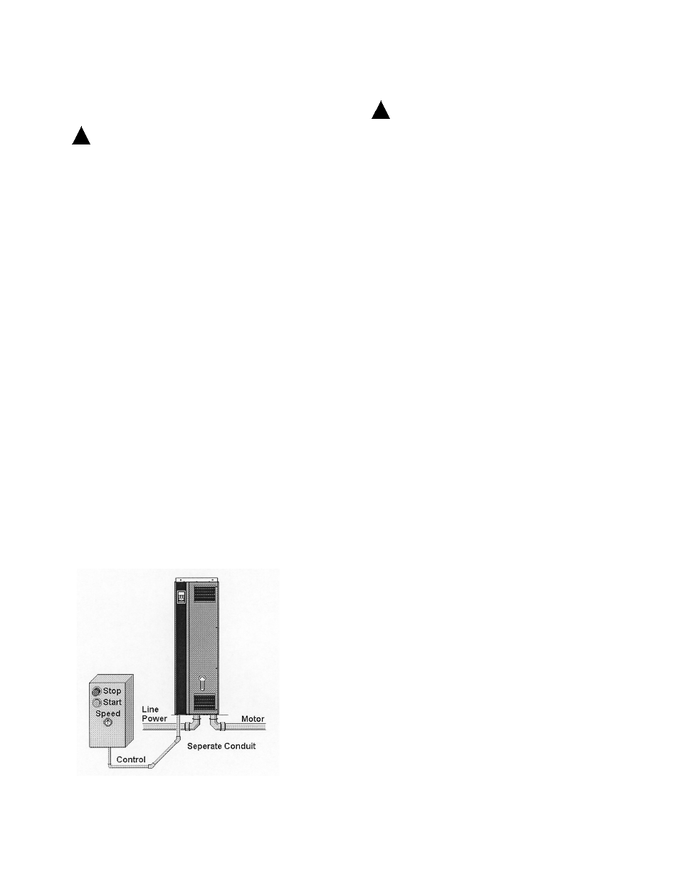
• Because the wiring from the option
enclosure to the motor carries high
frequency electrical pulses, it is important
that no other wires are run in this conduit. If
the incoming power wiring is run in the same
conduit as the motor wiring, these pulses
can couple electrical noise back onto the
building power grid.
At least three separate conduits must be connected
to the panel option. (See Figure 3-4.)
• Power wiring into the enclosure (and ground
back to the distribution panel)
• Power wiring from the enclosure to the
motor (and earth ground)
• Control wiring
Control wiring should always be isolated from the
high voltage power wiring.
Avoid getting metal chips into electronics.
Follow the connection procedures as illustrated in
the drawing provided with the unit.
For internal component identification, see Figure
3-5.
WARNING
!
E
quipmEnt
H
azard
!
r
otating
sHafts
and
ElEctrical
EquipmEnt
can
bE
Hazardous
. i
t
is
strongly
rEcommEndEd
tHat
all
ElEctrical
work
conform
to
all
national
and
local
rEgulations
. i
nstallation
,
start
-
up
,
and
maintEnancE
sHould
bE
pErformEd
only
by
qualifiEd
pErsonnEl
. f
ailurE
to
follow
local
rEgulations
could
rEsult
in
dEatH
or
sErious
injury
.
• Motor control equipment and electronic
controls are connected to hazardous line
voltages. Extreme care should be taken to
protect against electrical hazard.
• Proper protective grounding of the
equipment must be established. Ground
currents are higher than 3 mA.
• A dedicated ground wire is required.
• Wear safety glasses whenever working on
electric control or rotating equipment.
notE
m
akE
all
powEr
connEctions
witH
minimum
75
o
c
ratEd
coppEr
wiring
for
installations
in
n
ortH
a
mErica
.
Electrical Installation
Figure 3-4. Power Connections