Warning, Motor wiring – Bell & Gossett 176R0649C Technologic 502 Series Pump Controller User Manual
Page 16
16
Motor Wiring
WARNING
!
i
nducEd
v
oltagE
!
r
un
output
motor
cablEs
from
multiplE
drivEs
sEparatEly
.
i
nducEd
voltagE
from
output
motor
cablEs
run
togEtHEr
can
cHargE
EquipmEnt
capacitors
EvEn
witH
tHE
EquipmEnt
turnEd
off
and
lockEd
out
. f
ailurE
to
run
output
motor
cablEs
sEparatEly
could
rEsult
in
dEatH
or
sErious
injury
.
WARNING
!
w
iring
i
solation
!
r
un
input
powEr
,
motor
wiring
and
control
wiring
in
tHrEE
sEparatE
mEtallic
conduits
or
racEways
for
HigH
frEquEncy
noisE
isolation
. f
ailurE
to
isolatE
powEr
,
motor
and
control
wiring
could
rEsult
in
lEss
tHan
optimum
drivE
and
associatEd
EquipmEnt
pErformancE
.
• Motor wiring access panels are provided at
the base of the units as shown in Figure 3-6:
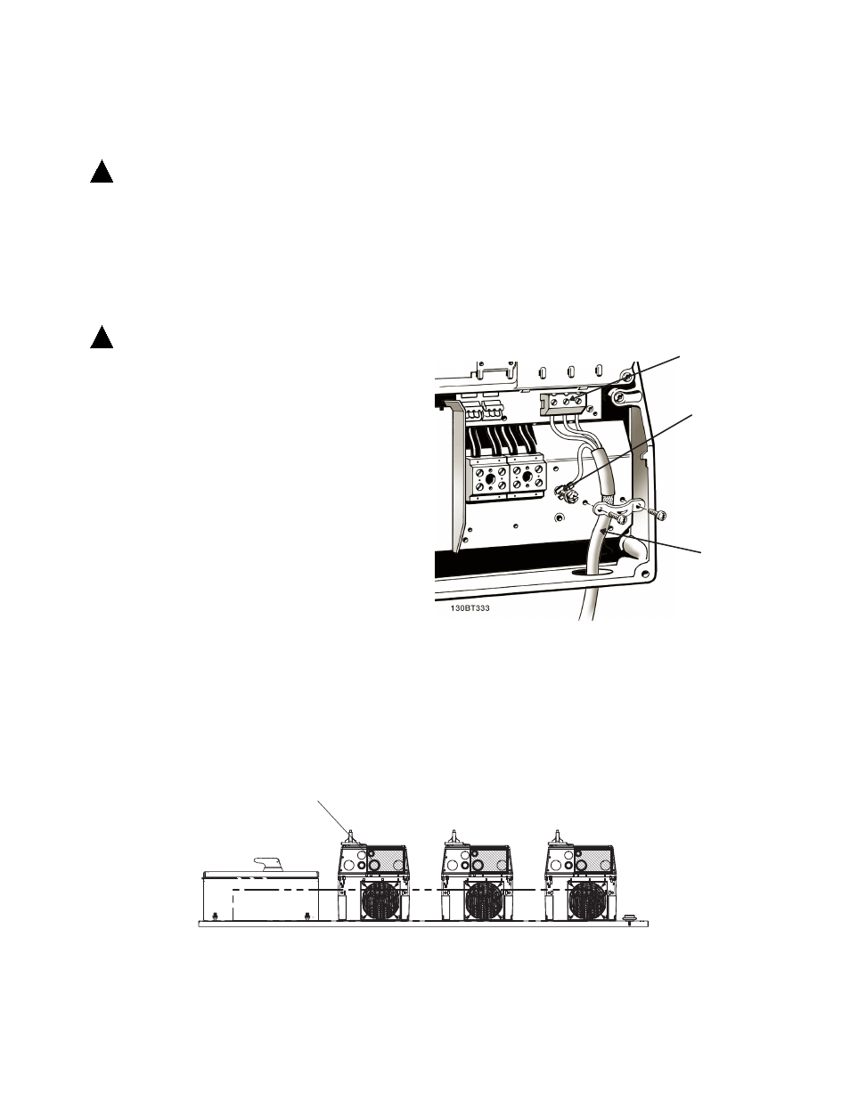
• Connect the 3-phase motor wiring to bypass
terminals T1 (U), T2 (V), and T3 (W). See
the connection drawing provided with unit.
• Depending on the configuration of the
equipment, motor wiring may be connected
to an electrical or mechanical overload, a
contactor, or terminal block (see Figure 3-7).
• Torque terminals in accordance with the
information provided in Table 3-2.
• Motor wiring should never exceed the
following maximum distances:
1000 ft (300m) for unshielded
500 ft (150m) for shielded
• Motor wiring should always be as short as
practical.
Figure 3-7. Sample Motor Wiring
Figure 3-6. Wiring Access Panels (bottom view)
Motor terminals
Ground
Motor wiring
T1, T2, T3
NOTE: CONNECT MOTOR LEADS
DIRECTLY TO VFD THROUGH ACCESS
PANEL. DO NOT ROUTE THROUGH
RACEWAY.
notE
s
EE
f
igurEs
3-12
and
3-13
for
powEr
,
motor
and
control
wiring
diagrams
.