Chapter 4: motherboard information 4-12 – Asus AP140R-E1 User Manual
Page 54
Chapter 4: Motherboard information
4-12
PSCH-LR
®
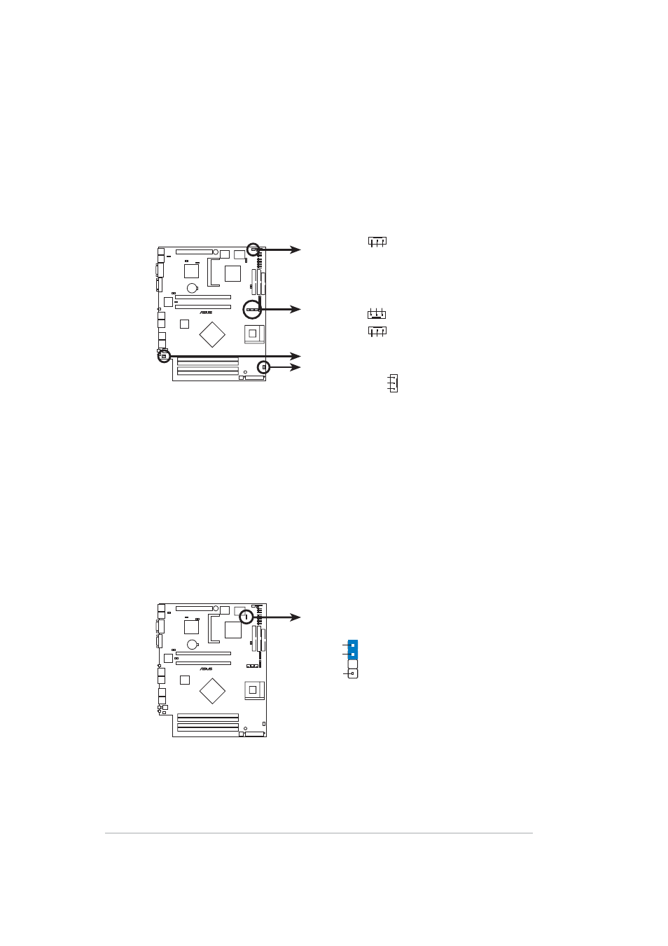
PSCH-LR 12-Volt Cooling Fan Power
FAN1
GND
Rotation
+12V
GND
Rotation
+12V
GND
Rotation
+12V
GND
Rotation
+12V
FAN2
FAN3
FAN4
FAN5
FAN6
7. Fan connectors (3-pin FAN1/2/3/4/5/6)
The fan connectors support cooling fans of 550mA~1100mA (13.2W
max.) or a total of 3.3A (39.6W max.) at +12V. Connect the fan cables
to the fan connectors on the motherboard, making sure that the black
wire of each cable matches the ground pin of the connector.
8. Chassis intrusion connector (4-1 pin CHASSIS1)
This lead is for a chassis designed with intrusion detection feature.
This requires an external detection mechanism such as a chassis
intrusion sensor or microswitch. When you remove any chassis
component, the sensor triggers and sends a high-level signal to this
lead to record a chassis intrusion event.
By default, the pins labeled “Chassis Signal” and “Ground” are shorted
with a jumper cap. If you wish to use the chassis intrusion detection
feature, remove the jumper cap from the pins.
PSCH-LR
®
PSCH-LR Chassis Alarm Lead
CHASSIS1
+5VSB_MB
Chassis Signal
GND
(Default)