1 motherboard layout, Chapter 4: motherboard information 4-2, Psch-lr – Asus AP140R-E1 User Manual
Page 44: Pci1
Chapter 4: Motherboard information
4-2
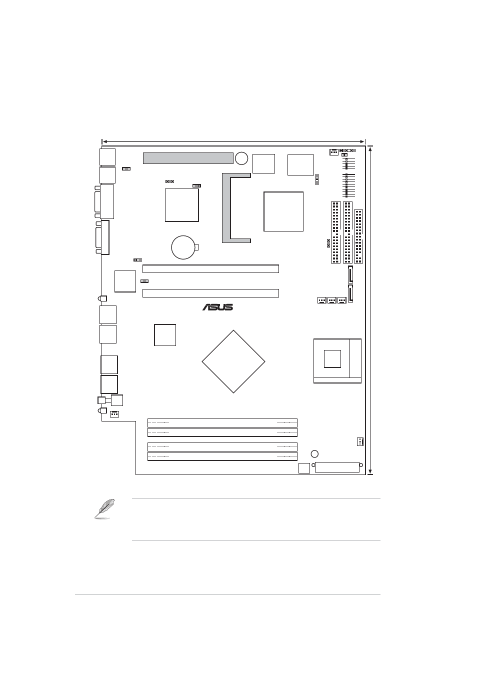
4.1 Motherboard layout
FAN5
PSCH-LR
25cm (9.9in)
31.1cm (12.2in)
BUZZER1
VGA1
SB_PWR1
BMCSOCKET1
CLRTC1
DDR DIMM_A1 (64/72 bit,184-pin module)
DDR DIMM_A2 (64/72 bit,184-pin module)
DDR DIMM_B1 (64/72 bit,184-pin module)
DDR DIMM_B2 (64/72 bit,184-pin module)
Intel
Canterwood-ES
MCH
FLOPPY1
PRI_IDE1
SEC_IDE1
Super
I/O
Socket 478
ATX Power Connector
CR2032 3V
Lithium Cell
CMOS Power
4Mbit
Firmware
Hub
SATA2
®
COM1
SATA1
FAN6
FAN2
FAN1
FAN3 FAN4
VGA_EN1
RECOVERY1
KBPWR1
PS2_KB1
PS2_MS1
LAN_EN2
LAN_EN1
PCIX1
PCIX2
LAN1
LAN2
USB1
USB2
SW1
LOCLED1
CHASSIS1
J3
BPSMB1
Intel
82547GI
Intel
Hance-Rapid
ICH
ATX12V1
MLED1
ATI
RAGE-XL
VGA
Controller
PCI1
USB34
P
ANEL1
Intel
82541GI
•
The PCI1 slot is used for debugging card only.
•
The BMCSOCKET1 slot is reserved for a server management
card.
- AP2500 (40 pages)
- AP1700-S5 (58 pages)
- RS700-E6/ERS4 (138 pages)
- AP1600R-E2(AA2) (150 pages)
- P7F-E (162 pages)
- RS161-E4/PA2 (126 pages)
- RS163-E4/RX4 (11 pages)
- M2N-LR (113 pages)
- P5BV/SAS (184 pages)
- K8N-DRE (142 pages)
- RS161-E5/PA2 (124 pages)
- LSI SAS3442X-R (68 pages)
- ESC4000/FDR G2 (200 pages)
- PIKE 2208 (16 pages)
- ESC4000 (162 pages)
- ESC4000 (22 pages)
- PSCH-SR/IDE (102 pages)
- P9D-M (156 pages)
- RS740-E7-RS24-EG (212 pages)
- P5M2-E/4L (12 pages)
- ESC2000 G2 (226 pages)
- TS700-E6/RS8 (166 pages)
- RS160-E3/PS4 (140 pages)
- PU-DLS (134 pages)
- TR-DLSR (100 pages)
- P5BV-C/2L (161 pages)
- TS100-E5/PI4 (166 pages)
- ESC1000 Personal SuperComputer (184 pages)
- NRL-LS (120 pages)
- PCI-DA2200 (369 pages)
- P8C WS (140 pages)
- RS120-E4/PA4 (174 pages)
- P5MT-M (150 pages)
- TS Mini (114 pages)
- TS Mini (2 pages)
- TS Mini (112 pages)
- P5MT-MX/C (156 pages)
- AP140R-E1 (52 pages)
- ASMB6-iKVM (114 pages)
- DSBF-D16 (202 pages)
- DSBF-D16/SAS (200 pages)
- RS160-E5 (164 pages)
- Z8PE-D12X (170 pages)
- Z8PE-D12X (168 pages)