Asus AP140R-E1 User Manual
Page 25
2-11
ASUS AP140R-E1 1U barebone server
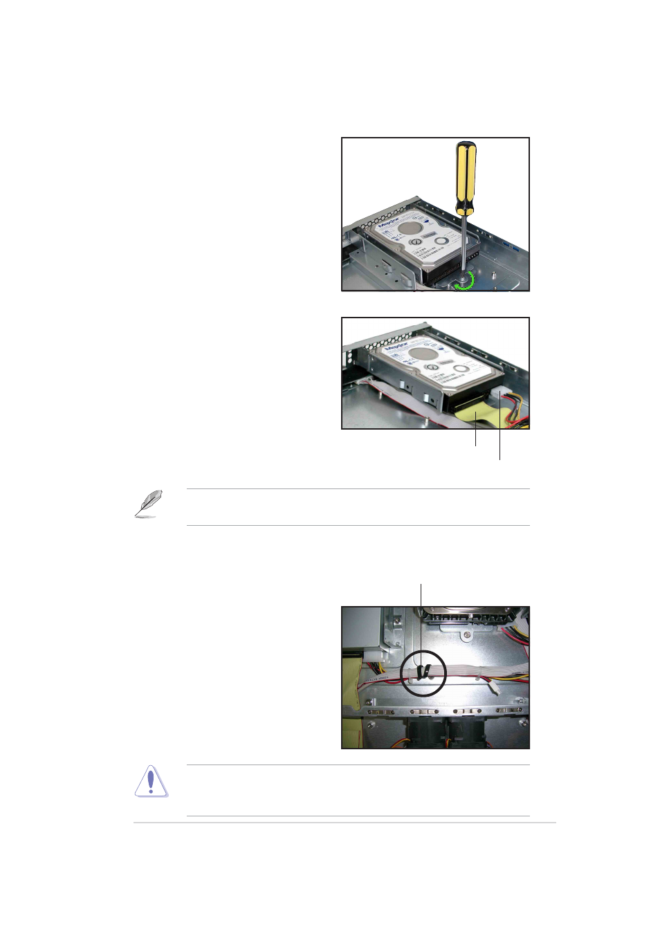
5. Connect the 40-pin IDE cable and
a 4-pin power plug to their
respective connectors on the
back of the drive.
4. Secure the tray with a screw.
40-pin IDE cable
4-pin power plug
The other end of the IDE cable is pre-connected to the primary IDE
connector on the motherboard.
6. Repeat steps 1 to 5 to install a second IDE drive.
7. When finished installing devices,
join the power and signal cables
together with the cable clamp to
prevent interference to the
rotating fan blades.
Cable clamp
Ensure that all cables are held together with the cable clamp, specially
those near the system fans. Loose cables may get caught with the fan
blades causing fan failure!
See also other documents in the category Asus Computer hardware:
- AP2500 (40 pages)
- AP1700-S5 (58 pages)
- RS700-E6/ERS4 (138 pages)
- AP1600R-E2(AA2) (150 pages)
- P7F-E (162 pages)
- RS161-E4/PA2 (126 pages)
- RS163-E4/RX4 (11 pages)
- M2N-LR (113 pages)
- P5BV/SAS (184 pages)
- K8N-DRE (142 pages)
- RS161-E5/PA2 (124 pages)
- LSI SAS3442X-R (68 pages)
- ESC4000/FDR G2 (200 pages)
- PIKE 2208 (16 pages)
- ESC4000 (162 pages)
- ESC4000 (22 pages)
- PSCH-SR/IDE (102 pages)
- P9D-M (156 pages)
- RS740-E7-RS24-EG (212 pages)
- P5M2-E/4L (12 pages)
- ESC2000 G2 (226 pages)
- TS700-E6/RS8 (166 pages)
- RS160-E3/PS4 (140 pages)
- PU-DLS (134 pages)
- TR-DLSR (100 pages)
- P5BV-C/2L (161 pages)
- TS100-E5/PI4 (166 pages)
- ESC1000 Personal SuperComputer (184 pages)
- NRL-LS (120 pages)
- PCI-DA2200 (369 pages)
- P8C WS (140 pages)
- RS120-E4/PA4 (174 pages)
- P5MT-M (150 pages)
- TS Mini (114 pages)
- TS Mini (2 pages)
- TS Mini (112 pages)
- P5MT-MX/C (156 pages)
- AP140R-E1 (52 pages)
- ASMB6-iKVM (114 pages)
- DSBF-D16 (202 pages)
- DSBF-D16/SAS (200 pages)
- RS160-E5 (164 pages)
- Z8PE-D12X (170 pages)
- Z8PE-D12X (168 pages)