3 connectors, Chapter 4: motherboard information 4-8 – Asus AP140R-E1 User Manual
Page 50
Chapter 4: Motherboard information
4-8
4.3 Connectors
This section describes the internal connectors on the motherboard.
Refer to section “1.4 Rear panel features” for information on the
external (rear panel) connectors.
PSCH-LR
®
PSCH-LR Floppy Disk Drive Connector
FLOPPY1
NOTE: Orient the red markings on
the floppy ribbon cable to PIN 1.
PIN 1
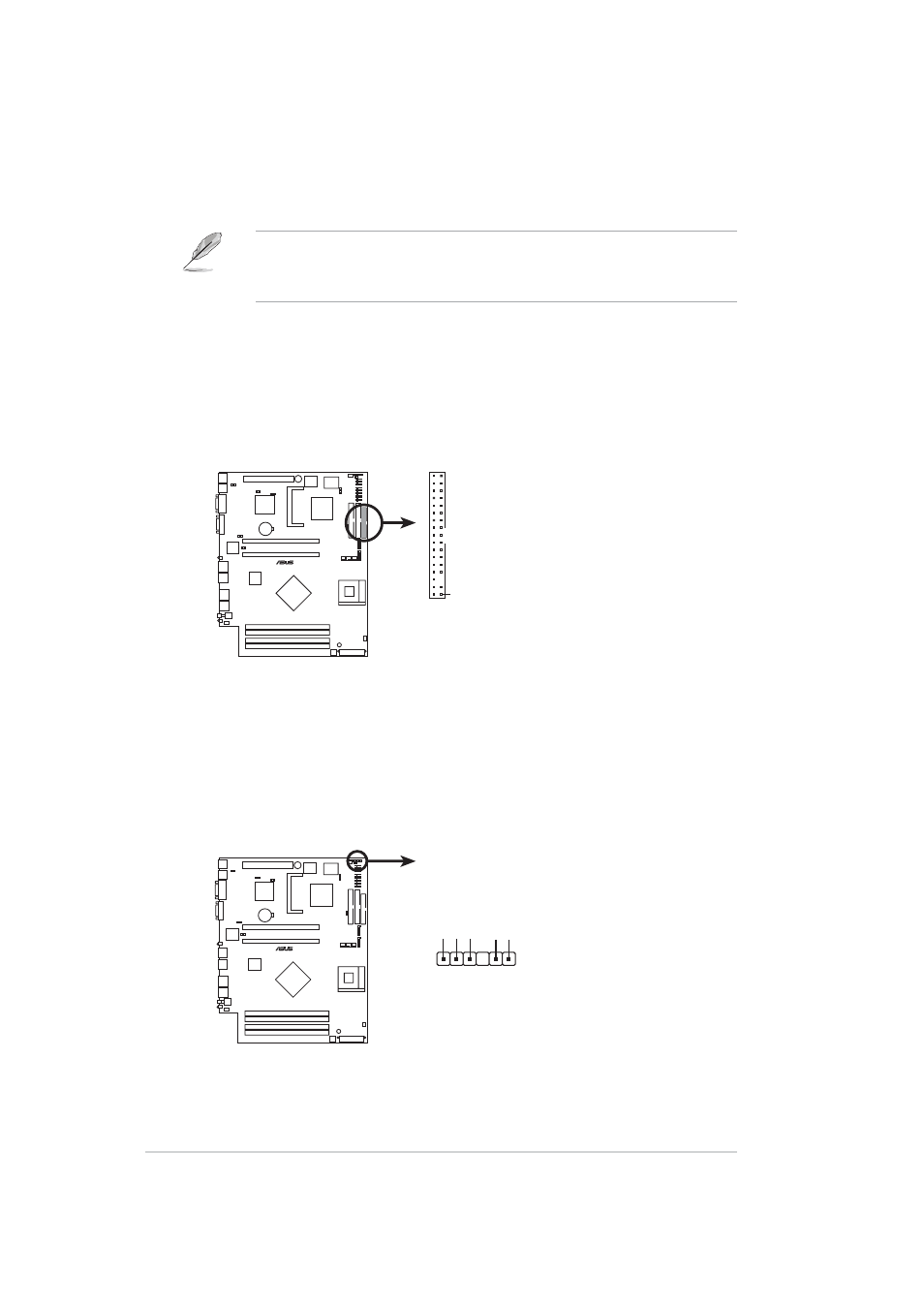
1. Floppy disk drive connector (34-1 pin FLOPPY1)
This connector supports the provided floppy drive ribbon cable. After
connecting one end to the motherboard, connect the other end to the
floppy drive. (Pin 5 is removed to prevent incorrect insertion when
using ribbon cables with pin 5 plug).
PSCH-LR
®
PSCH-LR SMB Connector
BPSMB1
1
SMBCLK
Ground
SMBDA
T
A
+3V
FLOA
TING
2. SMBus connector (6-1 pin BPSMB1)
This connector allows you to connect SMBus (System Management
Bus) devices. Devices communicate with an SMBus host and/or other
SMBus devices using the SMBus interface.
- AP2500 (40 pages)
- AP1700-S5 (58 pages)
- RS700-E6/ERS4 (138 pages)
- AP1600R-E2(AA2) (150 pages)
- P7F-E (162 pages)
- RS161-E4/PA2 (126 pages)
- RS163-E4/RX4 (11 pages)
- M2N-LR (113 pages)
- P5BV/SAS (184 pages)
- K8N-DRE (142 pages)
- RS161-E5/PA2 (124 pages)
- LSI SAS3442X-R (68 pages)
- ESC4000/FDR G2 (200 pages)
- PIKE 2208 (16 pages)
- ESC4000 (22 pages)
- ESC4000 (162 pages)
- PSCH-SR/IDE (102 pages)
- P9D-M (156 pages)
- RS740-E7-RS24-EG (212 pages)
- P5M2-E/4L (12 pages)
- ESC2000 G2 (226 pages)
- TS700-E6/RS8 (166 pages)
- RS160-E3/PS4 (140 pages)
- PU-DLS (134 pages)
- TR-DLSR (100 pages)
- P5BV-C/2L (161 pages)
- TS100-E5/PI4 (166 pages)
- ESC1000 Personal SuperComputer (184 pages)
- NRL-LS (120 pages)
- PCI-DA2200 (369 pages)
- P8C WS (140 pages)
- RS120-E4/PA4 (174 pages)
- P5MT-M (150 pages)
- TS Mini (114 pages)
- TS Mini (2 pages)
- TS Mini (112 pages)
- P5MT-MX/C (156 pages)
- AP140R-E1 (52 pages)
- ASMB6-iKVM (114 pages)
- DSBF-D16/SAS (200 pages)
- DSBF-D16 (202 pages)
- RS160-E5 (164 pages)
- Z8PE-D12X (168 pages)
- Z8PE-D12X (170 pages)